adsense analytic

Showing posts with label cad drawing. Show all posts

Wednesday, January 30, 2019

Top ten free floor plan software tools in 2019

Roomle 3D Floor Planner: Roomle belongs to a digital, 3D configurator useful for furniture designer to promote and demonstrate their stock. Roomle’s 2D and 3D room planning module facilitate real estate agents and interior designers to employ superior quality fascinating visuals for generating interactive floor plans. Roomle’s floor planner provides support to virtual walkthroughs and easy sharing capabilities.

PlanningWiz Floor Planner: PlanningWiz provides both floor plan design services and a floor planner solution. The software is useful at the time of designing both indoor and outdoor spaces. The purpose of PlanningWiz is to deal with the complexcities which particular industries may need while planning blueprints. It also provides tailored editions for designers in particular industries like property development or recreational facilities.

RoomSketcher: With RoomSketcher (previously known as RoomSketcher Home Designer) design application, the users will be able to generate floor plans and home designs in 3D. Both professionals and individuals get the ability to utilize RoomSketcher’s floor plans, 360-degree view photos, and interactive 3D walkthroughs. RoomSketcher users can depend on floor plans which are provided with exact measurements. The users will be able to render those plans in 3D and panorama, and even modify the finished home design with custom colors and textures.

Floorplanner: Floorplanner simplifies the process to generate floor plans in 2D and 3D and then distribute interactive versions of those floor plans online. Floorplanner comprises of an “auto-furnish” feature that allows you to simply decorate rooms inside your floor plan. Floorplanner produces professional and polished floor plans which are fully prepared for presentation.

Draft it: Cadlogic develops Draft it, a full-featured, 2D CAD drawing software that offers the architects with 3D modeling, drafting, and detailing tools. Draft it comprises with powerful drawing tools and supports the import of AutoCAD files and different design components and symbols.

Sweet Home 3D: Sweet Home 3D belongs to an open-source interior design application that can either be downloaded or applied in a web browser. It facilitates the users to observe the finished 2D floor plans in 3D for context and presentation. The program is compatible with Windows, Mac, and Linux operating systems.

SmartDraw: SmartDraw belongs to an org chart maker that provides an online floor plan creator for simple application, sharing and collaboration. SmartDraw’s chart and diagram templates are utilized to generate visuals for businesses which are simple to present. Anybody can utilize floor plan creator with an internet connection. SmartDraw contains various architectural design symbols and file sharing applications.

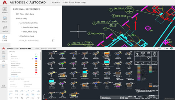
AutoCAD LT: AutoCAD LT belongs to a 2D CAD drafting and documentation software that is compatible with a Windows or Mac operating system. AutoCAD LT is the 2D version of AutoCAD, a stripped-down version with a reduced price tag. However, AutoCAD LT meets the technical diagramming and drafting requirements of contractors and construction companies.

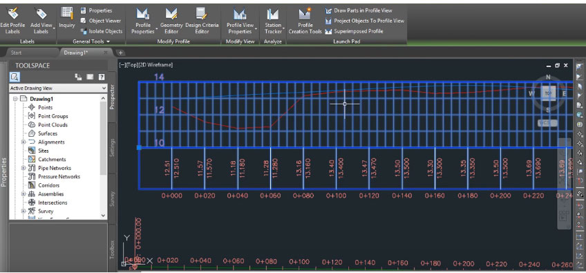
Civil 3D: Civil 3D from AutoDesk is a BIM solution specifically created for civil engineering design and construction companies, but its features can technically be applied to generate a 3D house plan. Civil 3D comprises of a set of surveying and civil engineering tools.

AutoCAD Architecture: AutoCAD Architecture contains a toolset that’s customized to the requirements of an architect. It utilizes AEC (architecture, engineering and construction) objects (that is, walls, doors, and windows) as design components and employs those symbols to generate realistic and spatially aware, three-dimensional floor plans.

Article Sourcelearn.g2crowd.com

Top ten free floor plan software tools in 2019

~~~~~~~~~~~~~~~~~~~~~~~~
Published By
Rajib Dey
www.bimoutsourcing.com
~~~~~~~~~~~~~~~~~~~~~~~~

Thursday, December 27, 2018

Learn to generate surface profile from file in AutoCAD Civil 3D

In this exclusive autocad tutorial, you will learn how to generate surface profile of existing road from file in AutoCAD Civil 3D. The surface will be created directly based on the labels and profiles. You don’t to draw surface separately. Initially, it is required to generate profile from file.

It is possible to generate a surface profile either from a horizontal alignment on a surface or from a surface profile file.

While generating a centerline profile, just produce one or more offset profiles simultaneously. Employ the Draw in Profile View option to illustrate the profile in the drawing.

Click Home tab > Create Design panel > Profile drop-down > Create Surface Profile Find.

In the Create Profile from Surface dialog box, in the Alignment list, choose the horizontal alignment to be utilized for the profile.

Make sure, that the surface to be utilized should be listed in the select surfaces list. If several surfaces are listed, apply Ctrl + click to choose one or more of them from which the profiles will be formed.

Optionally, in the Station Range area, indicate start and end stations if it is necessary for the profile to cover a distance under the entire length of the horizontal alignment.

Click Add to add the centerline profile to the Profile List.

Optionally, choose the Sample Offsets check box. Put the offset distances in the field if it is required for the profile to comprise one or more offsets from the centerline of the horizontal alignment. Apply positive numbers to indicate exact offsets, and negative numbers for left offsets. It is recommended to utilize commas to detach the values. As for instance : 20,-20,30,40.

Optionally, click Add to add the offset profiles to the Profile List.

In the table, to make analysis of the data for each profile line and make modifications when necessary.

Optionally, add or delete profiles in the Profile list.

Optionally, choose the Sample Offsets check box. Put the offset distances in the field if it is required for the profile to comprise one or more offsets from the centerline of the horizontal alignment. Apply positive numbers to indicate exact offsets, and negative numbers for left offsets. It is recommended to utilize commas to detach the values. As for instance : 20,-20,30,40.

In the table, to make analysis of the data for each profile line and make modifications when necessary. Optionally, add or delete profiles in the Profile list.

Perform one of the following:

If it is required to draw the profile in a profile view, click Draw In Profile View, and then opt for the create profile view method.

Click OK. The generated profiles are saved. If the alignment contains one or more profile views connected with it, the generated profiles are attached to the views.

Learn to generate surface profile from file in AutoCAD Civil 3D

Read more


~~~~~~~~~~~~~~~~~~~~~~~~
Published By
Rajib Dey
www.bimoutsourcing.com
~~~~~~~~~~~~~~~~~~~~~~~~

Monday, October 8, 2018

Details of CADS RC3D for Revit

The purpose of CADS RC3D is to simplify the placement, annotation and bar marking of reinforcing steel for all types of RC structures. CADS RC expands the robust reinforcement modelling strength of Revit.

By employing the 3D modelling functionality of Revit efficiently, CADS RC3D facilitates the rebar being splitted into particle groups (bar ranges). Besides, bar marks are formed and managed, detailed reinforcement (shop) drawings are produced with the single click of mouse.

Bar bending schedules are generated automatically and material lists are exported to external production software file formats like BVBs, aSa, Soulé and Excel.

With it’s user-friendly functionality, it is possible to produce 2D detailed reinforcement (shop) drawings from Revit models.

Unique annotation functions offer ticking & tagging of bar ends in different user-defined styles.

Supplementary annotation functions are generated to detail tapered ranges and mark rebar ends.

Modelled rebar is divided into physical zones inside each element of the structure.

Reinforcing bars are allotted to exact layers and accordingly viewed more smoothly.

Advanced editing functions facilitate rebar to be duplicated from one structure to another.

Various reinforcing bars are attached together to develop new, complicated bar shapes.

Trimming reinforcement is indicated and added around openings in the structure compliant with user’s preferences.

Rebar is trimmed and expanded to openings, detail or model lines.

Superior bar placement functions facilitates arranging new bars equivalent to other reinforcement already in the structure.

Generates Bar Bending Schedules (BBS) that adheres to UK, US and other country standards.

Reinforcement is ‘called off’ in the by element ‘release’ or ‘drawing sheet’ and then managed consequently.

The BBS and ‘bar lists’ are provided onto drawing sheets or printed with industry standard reporting templates

BBS and bar list templates can be easily tailored to abide by company standards.
Go through the following video tutorial, to get more clear idea.
Details of CADS RC3D for Revit

~~~~~~~~~~~~~~~~~~~~~~~~
Published By
Rajib Dey
www.bimoutsourcing.com
~~~~~~~~~~~~~~~~~~~~~~~~

Thursday, September 20, 2018

Autodesk launched AutoCAD Web App for AutoCAD users

Autodesk launched AutoCAD Web App. It is supported with AutoCAD’s RealDWG technology and graphics engine. This newest app provides you unmatched precision, stability and fidelity.

No installation is necessary for AutoCAD Web App. It is possible to access from any remote location and any web browser.

The AutoCAD web app is an extension of desktop application. The users will be able to avail different types of tools like PLINE, DIM, MTEXT, OFFSET, and TRIM in a user-friendly web interface to facilitate the users to view, edit, and annotate their DWGs in full swing.

The Command line is considered as the most impressive feature in the web app. With the arrival of the command line, the tasks become simplified. AutoCAD web app command line has the similarity with the command line accessible in AutoCAD and AutoCAD LT, just type commands and start drafting.

The command line provides extra functionality. The users can use commands along with sub-commands to execute more with the web app. As for instance, add and deduct area at the time of calculating areas; utilize continuous dimensions throughout the DIM command.

It is now possible to indicate a radius for FILLET or apply a keypad input to stipulate dimensions for a rectangle.
To get more details, go through the following link web.autocad.com

Autodesk launched AutoCAD Web App for AutoCAD users

~~~~~~~~~~~~~~~~~~~~~~~~
Published By
Rajib Dey
www.bimoutsourcing.com
~~~~~~~~~~~~~~~~~~~~~~~~


Saturday, July 7, 2018

nanoCAD 5.0 – The newest powerful CAD software

Nanosoft launched nanoCAD 5.0. It is a free, fully operative CAD software. After making registration and activating the software, the users can obtain a one-year renewable license and utilize the software for any purpose.

Once the software is installed, the users will be able to import drawing (DWG) files or develop new projects as well as export and share with others, devoid of any watermarks.

Top Three New Features of nanoCAD 5.0

nanoCAD provides support for DirectX graphics and it is now the standard for graphics performance for Microsoft Windows. DirectX is mostly recognized for gaming, but its graphics performance functions efficiently with computers and lower-end graphics cards. In nanoCAD 5.0, you can select which graphic library, OpenGL or DirectX, is considered as the perfect option for your video card. It can be accessed by opening the Options dialog box and selecting Graphic settings. (Image courtesy of Nanosoft.)

It is compatible with AutoCAD 2013/2014 version DWG files. nanoCAD can now read and write AutoCAD-supported DWG files which are well-suited with DWG files compatible with AutoCAD 2013.

Better object selection - The Quick Selection (QS) command is upgraded significantly and extended with a few vital capabilities. Now the users will be able to produce selection conditions for graphic primitives like arcs, polylines, splines and lines. The QS command in nanoCAD 5.0 also facilitates the users to produce selection conditions for complicated objects like tables, notes, dimensions and blocks.

The users can now add a block with .dxf file extension for greater adaptability.

nanoCAD products comprise of nanoCAD Plus, nanoCAD Pro, nanoCAD Mechanica, nanoCAD Construction, nanoCAD Construction Site.

To download nanoCAD 5.0, go through the following link nanocad.com

nanoCAD 5.0 – The newest powerful CAD software

~~~~~~~~~~~~~~~~~~~~~~~~
Published By
Rajib Dey
www.bimoutsourcing.com
~~~~~~~~~~~~~~~~~~~~~~~~

Tuesday, June 26, 2018

Steps associated with MEP Coordination Systems

MEP coordination is considered as one of the most vital process in construction that should be given special attention. The system makes sure that the structural framework and architectural design are not conflicted with its MEP-FP systems. Based on the level of details (LOD) and need of the client, the MEP coordination method differs in every organization. MEP Coordination Systems contains the following stages :-

1. Assessment of Consultant Design Drawings and Structural/Architectural Plans: Preliminary, the MEP coordination service facilitates the organization to obtain single line drawings from the MEP-contractors or consultants. Afterward, they study the structural and architectural plans thoroughly. Besides, they study the MEP specifications except for the assessment of drawings, layouts with reliability. Finally, MEP coordination services provider designs a brief plan for coordination.

2. 3D Prototype Formation: To fulfill the need in initial phase, the MEP coordinator generates an accurate 3D model by applying AutoCAD or Revit. This 3D model demonstrates total MEP services with adherence to the architectural and structural conditions of the building. Besides, this entire model acts as the base for various other important development-related plans, elevations or sections. MEP coordinator employs the 3D model for client inputs as well as generating complete walkthroughs.

3. Conflict detection and Resolution: In this phase, the 3D model set up earlier is tested for clashes among the MEP systems and the design elements. For this, they use Navisworks, a particular clash-detection software application. It detects all types of clashes like workflow clashes, geometry-related hard clashes, and clearance clashes. Besides, the MEP coordinator detects possible alternatives and deliver them to the clients.

4. Formation of Coordinated Sections and Drawings: Once a 3D model is tested for vertical and horizontal coordination, then the drawing sets are arranged to demonstrate how MEP-FP systems function in coordination as well as for more transparency, annotation and tagging process. The organizations who are liable to control MEP coordination can get elevation, section, and isometric views from the 3D model produced earlier. Besides, these can be applied for client explanations.

5. Formation of Detailed Service Drawings: In this stage, all the structural service-by-service drawings are generated and the details are included with reference to their dimensions like heights, and distances from gridlines. Site installation teams utilize these drawings and develop the base for fabrication drawings.

6. Formation of Spool, Fabrication Drawings, and Hangar Drawings: On basis of the scope of work, particular services drawings are utilized to generate fabrication drawings through some software or detailing. These drawings illustrate fabrication features for ductwork, and hence the CNC machines can directly identify them for rendering purposes.

If required, the MEP coordination unit also indicates the details of the model to create spooling data for production crews. Except for this, the firm can even plan out and then demonstrate the hangars for every design. As soon as the plan is made, the hangar specifications are provided on a list for the production units.

In MEP coordination systems, some steps may be omitted with regards to the scope of the project. Although each point is important for completing any project successfully devoid of any setbacks, additional cost, and unanticipated design amendments.

7. As-Fitted Modifications: This final step is associated with making modifications to the design model and the pictures because of some site changes from the construction designs. If the coordination work is perfect, and the installation is done according to the construction drawing directions and plans, the amendments to the as-fitted (also defined as as-installed and as-built) designs are least amount.

Source: blog.nibt.education

Steps associated with MEP Coordination Systems

~~~~~~~~~~~~~~~~~~~~~~~~
Published By
Rajib Dey
www.bimoutsourcing.com
~~~~~~~~~~~~~~~~~~~~~~~~

Thursday, June 14, 2018

Some useful AutoCAD commands to improve your CAD modeling skills

1) CHAMFER:- It is used to produce bevel about a corner.
Activation:- 
Alter Toolbar => Chamfer icon.
Alter menu => Chamfer option.
Type CHAMFER or CHA at “COMMAND:” prompt and press enter

2) PLOT :- It is applied to print the drawing on paper.
Activation:- 
Ctrl+P is the shortcut key
File menu => Plot option.
At “COMMAND:” prompt, type PLOT and press enter

3) LENGTHEN:- It is helpful for modifying the length of an accessible line. It is also possible to view the length of a selected line at command prompt.
Activation:- 
Alter toolbar => Lengthen option.
At “COMMAND:” prompt, type LENGTHEN or LEN and press enter
4) XLINE (Construction Line) :- It is a useful command to generate a endless line.
Activation:- 
Draw toolbar => Construction Line icon.
Draw menu => Construction Line option.
Type XLINE or XL and press enter at “COMMAND:” prompt.

5) ATTDEF (Attribute Definition) :- It is applied to include block attribute to a block. An attribute stands for a label or tag that connects data to a block.
Activation:- 
Draw menu => Block option => Describe Attribute option.

Type ATTDEF or ATT and press enter at “COMMAND:” prompt.

6) INSERT :- It is suitable for inserting an accessible Block in the active file.
Activation:- 
Draw toolbar => Insert Block icon.
Insert menu => Block option.

Type INSERT or I and press enter at “COMMAND:” prompt.
7) WRITE BLOCK :- It is utilized to generate a New Block. When Write Block command is applied to produce Block, the resultant block is applicable in any AutoCAD File.
Activation:- 
Type WBLOCK and press enter at “COMMAND:” prompt.
8) BLOCK :- It is applied to make a New Block. When Block command is used to produce the block, the resultant block is employed in the source file only.
Activation:-
Type BLOCK and press enter at “COMMAND:” prompt.
9) DIVIDE :- This command is applied to Divide an object into several identical divisions.

Activation:- 
Draw menu => Point option Divide option.

Type DIVIDE or DIV and press enter at “COMMAND:” prompt.
10) MEASURE :- This command is utilized to break up an object into some divisions of defined equivalent length.
Activation:-
Draw menu => Point option Measure option.
Type MEASURE or ME and press enter at “COMMAND:” prompt.
To get more commands, go through the following link mycivil.engineer

Some useful AutoCAD commands to improve your CAD modeling skills

~~~~~~~~~~~~~~~~~~~~~~~~
Published By
Rajib Dey
www.bimoutsourcing.com
~~~~~~~~~~~~~~~~~~~~~~~~

Friday, August 11, 2017

Advance Steel – Status Control Inside Model And Drawings

In Advance Steel, the users can use the options to provide a Status level to both the drawing and the model elements and it is often described as Key Stages/Life Cycles inside the production process.

The Status system remains as part of the Fabrication data inside Advance Steel, it can contain levels/statuses which are included to it through the Management Tool (MT) System. Besides, comment levels are included to approve the status.

Various colors can be arranged while generating anything inside the MT. These can then be applied to provide colourisation/highlighting to the model. It is accomplished with the project explorer and the saved Query Feature.
Together with this, there exist a status level for drawings, the drawing system is segregated to the model elements, because drawings may not always remain at the equivalent status as the model, as for instance the model may be left for revision, the elements in the model are updated, but the drawings are not located at similar point. But at some point, they will obtain an adjustment, then a modification in status level of Reissued etc., then modifying to the same status as model at some point.

The vital fact is that a “STATUS” level, is not an adjustment to the drawing, it belongs to the present state of the drawing to the overall life cycle to the project, so the two systems are not same, but can be employed in combination to deliver a life cycle management to the system for Autodesk Advance Steel document and model management.


To get detailed idea on the different steps and operation, go through the following video presentations.


Read more

~~~~~~~~~~~~~~~~~~~~~~~~
Published By
Rajib Dey
www.bimoutsourcing.com

~~~~~~~~~~~~~~~~~~~~~~~~

Sunday, January 1, 2017

Download Sample Cad Drawing Of Inclined Pitched Roof Concrete Slab Reinforcement

This is a Dwg CAD drawing sample of an Inclined Pitched Roof Concrete Slab Reinforcement. Plan view of a reinforced concrete pitched-inclined slab demonstrates exact positioning of slab reinforcement, cantilever reinforcement, slab thickness, roof apex reinforcement.

Illustration of a 12x12m roof slab with a 4 by 4 column-beam support layout. Reinforcement calculations are done by applying Eurocode 2. Design of slabs is accomplished so as to leave out the deflection checks.

The sample drawing covers the following items :-

• full pitched roof slab reinforcement plan view
• slab & overhang cantilever reinforcement
• roof pitched apex reinforcement
• slab thickness annotation

This comprehensive drawing is available in CAD dwg, dxf and pdf formats and can be applied in any projects and save significant time.

Link for Download sample cad drawing of Inclined Pitched Roof Concrete Slab Reinforcement

Download sample cad drawing of Inclined Pitched Roof Concrete Slab Reinforcement

~~~~~~~~~~~~~~~~~~~~~
Published By
Rajib Dey
~~~~~~~~~~~~~~~~~~~~~

Tuesday, July 26, 2016

How to import CAD drawing of Jhali Wall into Revit & generate Adaptive Component/Family (Jhali Wall)

Learn the role footings play in keeping foundations from settling and how to size them properly for soil conditions.

This Revit tutorial is based on how to generate adaptive component for Jhali Wall in Revit. Adaptive component is ideal to produce Jhali wall as the size of component can be easily modified according to your choice. There exist 3 templates for developing adaptive components but in this Revit tutorial, specific curtain panel pattern is utilized to produce Jhali wall.

Open the curtain panel pattern based template to view grid system that is truly tile pattern, reference lines (in green color) and points which refer to adaptive points. Adaptive points contain numbers on them. These adaptive points, grid system and reference lines are modifiable.

Jhali Wall is created with AutoCAD and the CAD drawing for Jhali Wall is imported to Revit.


~~~~~~~~~~~~~~~~~~~~~~
Published By
Rajib Dey
~~~~~~~~~~~~~~~~~~~~~~