adsense analytic

Showing posts with label 3D House. Show all posts

Saturday, March 2, 2019

How to design a 3D house in AutoCAD

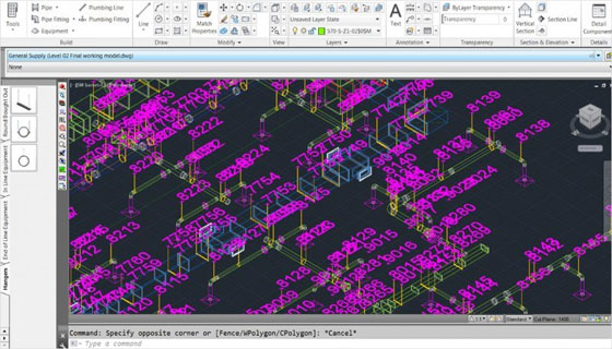
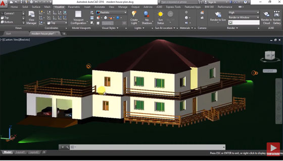
In this exclusive AutoCAD tutorial, you will learn how to use AutoCAD to make a complete 3D house from 2D plan.

The different types of useful AutoCAD commands are used in this tutorial which are given below :-

UN (unit command) – It manages the accuracy and display formats toward coordinates, distances and angles.

DIM (dimension style manager) – It makes several dimensions and types of dimensions with a single command. It is possible to select objects or points on objects to dimension, and then click to set the dimension line.

Rectang (create a rectangle) – It is used to form a rectangular polyline from given rectangle parameters (length, width, rotation) and type of corners (fillet, chamfer, or square).

PLINE (select poly line tool) – It is applied to produce a 2D polyline, a single object that is made of line and arc segments.

LINE (to draw line) – It is utilized to make a wide array of adjacent line segments. Every segment belongs to a line object that is editable independently.

OFFSET – It is applied to create parallel or concentric copies of lines, polylines, circles, arcs, or splines).

TRIM (modify existing objects) – It is applied to trim objects to comply with the edges of other objects.

MI (mirror objects) – It is applied to generate a mirrored copy of a selected object.

COPY (to copy any object) – It is used to copy objects to a specific distance in a specified direction.

STRETCH – It is employed to stretch objects passed by a selection window or polygon. STRETCH only moves the vertices and endpoints located inside the crossing selection.

ROTATE – It is used to rotate selected objects around a base point to an absolute angle.

MOVE – It allows to move objects to a specified distance in a specified direction. The objects are moved accurately with coordinates, grid snaps, object snaps, and other tools .

To learn the detail 3d modeling process in AutoCAD, go through the following video tutorial.

Video Source: CADD MANIAC
How to design a 3D house in AutoCAD
~~~~~~~~~~~~~~~~~~~~~~~~
Published By
Rajib Dey
www.bimoutsourcing.com
~~~~~~~~~~~~~~~~~~~~~~~~

Wednesday, November 29, 2017

BIM based Point Layout Software is ideal for surveying professionals

Autodesk Inc. has developed Point Layout software to perform layout on the construction site accurately. This software can simplify the surveying process by maintaining the perfectness of the model to the job site for contractors and subcontractors.

It applies model coordinate information at the construction site to enhance office-to-field efficiency and QA/QC, curtail rework, and improve layout productivity.


The software generates points on almost any object and export point locations to a series of robotic instruments.

The software offers the following exclusive features

Generate points: Generate points inside drawings and models produced through AutoCAD, Revit, or Navisworks software.

Export to robotic instruments: Export points from AutoCAD, Revit, or Navisworks software to a total station or other robotic instrument to keep the layout of the construction accurate.

Import field conditions: Import staked point locations back into AutoCAD, Revit, or Navisworks software to facilitate generating an as-built model for handoff.

Export to Navisworks: Export your work from AutoCAD or Revit software and import it into Navisworks software to modify your point locations throughout the coordination process.

Control points: Add, import, and export control points to your model. Control points can comprise of automatic grid intersection placement, import, and manual placement in AutoCAD and Revit software.

Coordinate systems: Include coordinate systems to your model that match the job site. This allows you to align your points with the entire construction project.

3D-model based layout: Incorporeate with the BIM 360 Layout iPad app and manage your layout from the entire model.

Compare points: Utilize imported field points with field deviation reports for QA/QC, then pass issues to BIM 360 Field software for resolution.

Slab analysis: Import field or as-built points of any surface into Revit software for deviation analysis of field against the design model.

To download the trial version of Point Layout, click on the following link www.cesdb.com

BIM based Point Layout Software is ideal for surveying professionals

~~~~~~~~~~~~~~~~~~~~~~~~
Published By
Rajib Dey
www.bimoutsourcing.com
~~~~~~~~~~~~~~~~~~~~~~~~