adsense analytic

Wednesday, December 31, 2014

Energy Analysis for Autodesk Revit

This exclusive video tutorial is presented by majentauk.Compare estimated energy and lifecycle costs. Energy Analysis for Autodesk Revit software is a cloud-based energy simulation service powered by Autodesk Green Building Studio that supports sustainable design.

This service is available with the purchase of Autodesk Subscription or rental licenses for select Autodesk products.


~~~~~~~~~~~~~~~~~~~
Publishing By
Rajib Dey
~~~~~~~~~~~~~~~~~~~

Tuesday, December 30, 2014

Some handy BIM/VDC-associated technologies which can make a sea change in AEC Firms

The workflows of AEC firms are improved to a great extent with the implementation of building information modeling & virtual design and construction. Several upgraded techniques emerge out to transform 3d co-ordination process to a superior level.

The followings are some handy BIM/VDC-associated technology trends which facilitate the building team to design, build as well as operate buildings efficiently in the future course of time.

3D laser scanning: Lots of softwares contain less expensive field scanning techniques which perform through BIM models having perfect field information for construction sites. A scan is performed through the strong laser recording of the building structure that gathers the shape and look of a site. These conditions are transformed into a cloud of data points which are imported into a BIM model.

On a solo project, 30 minutes of scan time in the jobsite and 30 minutes of post-processing and uploading the point cloud into a Revit model can lead to saving of $30,000.

Model energy performance on the fly: With the emergence of new software tools, energy analysis of a building is executed throughout the conceptual design stage. Autodesk and Sefaira have launched various applications facilitating designers to accomplish energy study of early concepts on the fly. These applications compact the time required for assembling and crunching energy performance data for a long period. It facilitates the design teams to adapt their designs on the fly on the basis of the data.

Prefabrication will transform building delivery: Several Building Teams are applying BIM methods to collude with general contractors and construction managers to prefabricate and set up building components which range from mechanical equipment, plumbing infrastructure, and even complete restroom pods.

BIM makes the prefabrication process easy and smooth as the design become constructible in the model to be prefabricated and installed.

Data management: Some leading software companies like Assemble Systems and Panzura have built up cloud-based devices to manage, preserve, and distribute project data in a sophisticated way.

Computer-aided manufacturing: With the arrival of prefabrication and manufacturing processes like Lean construction, it opens savings and process efficiencies, the AEC are compelled to comply much the identical way computer-aided manufacturing changed manufacturing. Various CAM technologies together with BIM processes can deliver ready-to-install modules.

Some handy BIM/VDC-associated technologies which can make a sea change in AEC Firms
Image Courtesy: www.bdcnetwork.com

Ref.: http://www.bdcnetwork.com/

~~~~~~~~~~~~~~~~~~~
Published By
Rajib Dey
~~~~~~~~~~~~~~~~~~~

Monday, December 29, 2014

Making the stair with Revit 2015

This is an amazing video which show how to create a staircase in the project in Autodesk Revit 2015. For this, it is important to learn anatomy of a stair and making the basic structure. Creation of a draft with model lines is very important. Then it is the time to make the landing and railing.

Here is the detail tutorial video:


How to render sketchup model in Revit

~~~~~~~~~~~~~~~~~~~
Published By
Rajib Dey
~~~~~~~~~~~~~~~~~~~

Sunday, December 28, 2014

Modeling Roof Formations Structures and Materials in Revit

This is actually an amazing tutorial video where shows how residential roof can be form., what is the material and structure.

Here various roof tools are used. There are also various roof forms here, it need to be accustomd with the forms before fix it in the design.


This video will give the detail:


Modeling Roof Formations Structures and Materials in Revit

For more detail hit into this link

~~~~~~~~~~~~~~~~~~~
Published By
Rajib Dey
~~~~~~~~~~~~~~~~~~~

Thursday, December 25, 2014

How to find out the required time while completing a drawing in Autocad

Sometimes, it becomes necessary to know the time for completing a drawing in autocad (required by client for billing purpose) or evaluate your skill for completing the drawing with autocad in quickest possible time. All these are possible, if you use the ‘TIME’ command in autocad to find out the required time automatically while working on a drawing.

In order to apply the time command, provide time on the command section, the following records will be visible:-

  • Current time: It will display the present time along with the date

  • Created: The date and time for the creation of the drawing

  • Last updated: The time once the drawing was last saved

  • Total editing time: The accrued time incurred in drawing creation from session to session. AutoCAD does not take in plotting time or working time but quit devoid of saving your alterations

  • Elapsed timer: Also preserve time used in the drawing, but this can be activated or deactivated as well reorganized.

  • Next automatic save in: Notify you when your drawing will be saved automatically. You can set how frequently you save your drawing automatically. Just apply the OPTIONS command and display the Open and Save tab.

  • Next is the Enter option [Display/ON/OFF/Reset]: prompt. Following are the functionalities of these options:
    Display: Updates the listing by present times
    ON and OFF: Turns the elapsed time on and off
    Reset: Resets the elapsed time to zero

So these options are useful to help you in finding out the required time for completing a drawing.

Other option: The Express Tools EDITTIME command (type it on the command line) detects active editing time. It will function in a better way as compared to time command to represent your actual work perfectly. For start tracking, it should be activated. You can reset the time and apply the timeout option to postpone counting after a specific time of inactivity.

How to find out the required time while completing a drawing in Autocad

Image Courtesy: autocad-architecture-blog.com

Ref.: http://www.ellenfinkelstein.com

~~~~~~~~~~~~~~~~~~~
Published By
Rajib Dey
~~~~~~~~~~~~~~~~~~~

Tuesday, December 23, 2014

How Haskell uses 3d laser scanning technology for water retrieval project

Laser Scanning is a very useful technology for 3d modelers. It is a one kind of survey device that facilitates the users to get exact measurements in complex surroundings. The device gathers survey data points at the speed of 50,000 points per second and contains an successful range of 400 to 500 feet. Just arrange scan setups within the facility and you will get the complete 3D model that can be applied to generate 2D civil or architectural drawings, 3D computer models as well as final survey documents.


Watch the following live demonstration through youtube which shows how Haskell, a leading USA basedarchitectureengineering, and construction firm, has recently applied 3d laser scanning technique in a water retrieval project.


~~~~~~~~~~~~~~~~~~~
Published By
Rajib Dey
~~~~~~~~~~~~~~~~~~~

Monday, December 22, 2014

Learn to draw topography lines with AutoCAD

Rob Koningen, associated with UrbanLISP, has presented a tutorial based video that shows how to draw topography lines with AutoCAD.


The landscape architect can view topography and slopes through sections. The topography is presented in the plan drawing. Several landscape architectsprefer to draw slope lines. Slope lines are the pattern of lines that direct from the top of the slope to the bottom.

Each second line finishes one half of that distance. It is very easy to draw similar type of pattern on straight lines through AutoCAD. But it becomes difficult to draw pattern if the slopes in the concerned plan are loopy types.

The UrbanLISP ‘Slopelines’ command in AutoCAD facilitates the users to draw such a pattern in a quickest possible way.


~~~~~~~~~~~~~~~~~~~~
Published By
Rajib Dey
~~~~~~~~~~~~~~~~~~~~

Ideate, Inc. introduced Ideate Explorer for Revit 2015.1

Ideate, Inc., the most recognized authorized Developer of Autodesk as well as Autodesk Gold Value Added Reseller, just launched Ideate Explorer for Revit 2015.1.

This Ideate Software solution comes with some advanced features & superior functionalities. The users can now enjoy a modeless interface. The users can now perform simultaneously in the Autodesk Revit and the Ideate Explorer for Revit surroundings.

This latest Ideate Explorer for Revit will provide a wide array of benefits to the BIM and virtual design and construction (VDC) managers, project leaders, facility managers, architects, engineers, and other users in support of model auditing, power selection and model maintenance. This newest 3d modeling application will facilitate the users to obtain the global view of model contents and trace, segregate, revise and/or efficiently delete unnecessary components from the Revit model.

The ideate customers can explore their Revit files effortlessly by performing through Revit and Ideate Explorer concurrently.

With the new Ideate Explorer, AEC customers can get superior speed and fluidity in their revit solutions.

Following are some of the crucial features of Ideate Explorer for Revit:-

  • Ability to view elements instantly in the model and recognize mistakes.
  • Explore, filter, compute and opt for more than 10,000,00 elements in a Revit Model.
  • Ability to locate which workset elements are active and it is useful for the QA process.
  • Discover lost and incorrect objects.

The users can access Ideate Explorer for Revit with a non-commercial free trial version from Autodesk Exchange Apps Store.

For getting more updates, call 888.662.7238, contactsales@ideatesoftware.com, and for support, contactsupport@ideatesoftware.com

Ideate, Inc. introduced Ideate Explorer for Revit 2015.1

~~~~~~~~~~~~~~~~~~~
Published By
Rajib Dey
~~~~~~~~~~~~~~~~~~~

Saturday, December 20, 2014

Solidworks 2015 beta, the most updated version of Solidworks

Ideas Design Solutions just introduced beta version of SOLIDWORKS® 2015. This newest version of this cad software contains various advanced features like easy geometry formation, quicker simulation analysis, improved cost analysis, and superior amalgamation with downstream progressions which can enhance your engineering & design output.


SOLIDWORKS® 2015 will mainly highlight the following areas - Streamline Productivity; Make your workflow perfect; reduce production costs and resolve challenges.

  • Boost up day-to-day Productivity: Superior engineering and design performance facilitates to perform work quickly, easily and efficiently.
  • Make superior process: Allocate project information amid the global team through least endeavor.
  • Minimize Operations Costs: Design gets nearer to downstream practices and incorporated with manufacturing in a better way.
  • Work out more design challenges: SOLIDWORKS 2015 brings new technical capabilities that support diversified industries and markets.


www.solidworks.com

~~~~~~~~~~~~~~~~~~~
Published By
Rajib Dey
www.bimoutsourcing.com
~~~~~~~~~~~~~~~~~~~

Thursday, December 18, 2014

Some easy to follow steps for creating flat roof with Autocad

AutoCAD contains diversified roof commands which are used to generate various types of simple or complicated as well as flat to sloped roofs. After generating the roofs, one can revise them by altering their heights and slopes and inserting dormer windows. Any object can also be transformed into roofand the roof can also be modified.


In order to create a flat roof, the rise for the flat roof is assigned to a very low number and the overhang is assigned to 0".

Mohammed Sabir, a renowned trainer and consultant in Computer Aided Drafting & Design (CADD), has presented an exclusive video that focuses on how to produce a flat roof quickly and easily through autocad involving all essential elements like Roof slab , Parapet , Beading etc.


~~~~~~~~~~~~~~~~~~~
Published By
Rajib Dey
~~~~~~~~~~~~~~~~~~~

Building Lifecycle Management (BLM) and its various advantages

Building Lifecycle Management (BLM) can be termed as a process for designing, assembling, and maneuvering a facility with a single set of interoperable data.

BLM employs a BIM Level 3 approach to allow a exceedingly developed Extended Collaboration process set up on the basis of Manufacturing industry best practices. BIM Level 3 will help in improving construction standardization, long-standing value for project owners as well as profit sharing for AEC project contributors.

BLM functions through a strong Product Lifecycle Management (PLM) system that produces a well-organized environment to organize complicated data associated with AEC (Architecture, Engineering & Construction) industry.

A BLM system is originated with the inclusion of BIM data to a PLM system.

BLM offers a wide array of significant advantages which range from better productivity, sustainability, and quality, as well as reduced waste, risk, and cost. BLM brings these advantages by disposing of rework, lessening RFIs (Requests For Information), consolidating data, contextualizing information and most of all forecasting outcomes perfectly.


As the data are consolidated centrally, it facilitates eliminating version control issues, possibilities for individual error, and even the requirement to handle files.

The users will be able to avail a single live database through web services and get rid of the issues like , rework (e.g., unnecessary drawings) and frequentness to a great extent.

With a BLM system, the users can solve any problem practically in advance. So occurrence of faulty RFIs, submittals, and change orders are minimized significantly.

Designers will be able to undertake more informed decisions inside a wealthy data context and keep up superior control over the quality of the finished product through BLM.

By working together under a BLM environment, the construction firms and building systems manufacturers can get the clear ideas on project requirements. By getting authentic data, builders and suppliers can make the coordination process better and understand the design intent efficiently.

BLM is formed to minimize waste by forecasting outcomes perfectly as well as detecting prospective clashes and optimizing practices. It will prevent expected cost overruns and standard risk margins.

By following the same system, BLM also minimizes risk to the project schedule, worker safety, and construction budget generally.

Manufactured systems like curtain walls and fac¸ades are considered as the most complex and expensive constituents of a construction project. The fac¸ade includes 15 percent of a construction budget. Generally Fac¸ade models do not involve data on the fabrication process, but manufacturing time can be trim down to a great extent (nearly up to 50 percent) if the fabrication process is identified in the design phase. A BLM system with transactable BIM data can make a strong collaboration amid the designer and the fac¸ade manufacturer.

While performing with building product manufacturers, the designers provide guarantee that the design intent is recognized and supply chain efficiency is enhanced, the whole project will be benefited.

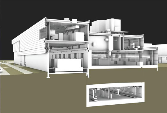
BIM data from a series of systems are resolved inside the BLM environment, where issues are recognized and marked for further processing.

Building Lifecycle Management (BLM) and its various advantages

Image Courtesy : skybim.com


~~~~~~~~~~~~~~~~~~~
Published By
Rajib Dey
~~~~~~~~~~~~~~~~~~~

Wednesday, December 17, 2014

Rhino3DPRINT 2015 is a cad based 3d modeling software to prepare your 3D data for printing

MecSoft, California based leading solution provider in CAD/CAM software, will launch Rhino3DPRINT 2015 software very soon. It is a completely incorporated, individually licensed plugin that is compatible with the Rhinoceros 5.0 NURBS modeler.

Rhino3DPRINT 2015 software contains some simplified & automatic tools for generating 3d data like point clouds and meshes. One will be able to deal with data virtually as well as 3d print models from various input sources and leading 3d formats which range from scanners, digitizers, bitmaps, point clouds, and more.

The software consists of the following exclusive features:

  • Browser-supported user interface – Apply an easy to use ribbon UI to get all the accessible tools.
  • Point Cloud Processing – Generate meshes out of point clouds smoothly.
  • Boolean Operations – Instantly execute severalBoolean operations like Union, Subtraction and Intersection connecting mesh solids.
  • 3D Printing Functions – Perform an analysis before starting printing work and at the same time arranging a 3D model to a particular print volume.
  • Mesh Inspection – Use methods like curvature & reflection line analysis to assess the smoothness of a model using techniques such as.
  • Mesh Reduction –Lessen the number of triangles to a great extent inside a model, whereas keeping the basic shape unchanged.
  • Mesh Healing – Automate the healing and analysis of holes inside a mesh.
  • Mesh Refinement – Filter a specified mesh for 3D printing.
  • Mesh Smoothing – Chaotic models become easily printable with smooth meshes.
  • Mesh Offsetting – Effortlessly offset objects inside a model through standardized distances.
  • Mesh Shelling – Divide and then cap two offset models to generate shells.
  • Mesh Slicing – Produce definite curvatures through a slicing tool.
  • Mesh Analysis & Repair – Evaluate meshes for problem areas (that may occur at the time of 3D printing) and repair them .
  • Mesh Hulling – Make ‘gift wrap’ meshes through convex hulls.


Rhino3DPRINT 2015 is a cad based 3d modeling software to prepare your 3D data for printing

Image Courtesy: 3dprint.com

~~~~~~~~~~~~~~~~~~~
Published By
Rajib Dey
~~~~~~~~~~~~~~~~~~~

Tuesday, December 16, 2014

Make real-time design analysis of Mechanical Systems with Sefaira’s latest software

Sefaira, the leading software developer for high-performance building design, will be going to release a new program that provides huge benefits to HVAC design engineers to efficiently work together with architects and HVAC designers from the initial design phase, by amalgamating performance analysis and building information modeling (BIM) workflows and spreading them across several members of the project team.

Sefaira expects to launch this new program before 2015. For getting superior results, Sefaira will apply EnergyPlus engine to provide real-time design analysis of mechanical systems and envelope options as well get desired results in quickest possible time. This newest program can be used to examinearchitectural models. The program will reduce the engineer’s requirements to reconstruct models from the beginning. Thus the engineers will be able to perform proactively with architects to realize the effect of design modifications and crucial parameters associated with mechanical system.

Due to technical hindrances, the communication amid architects & engineers is obstructed. Engineers generally reconstruct an architect’s model from the beginning before they can carry out any analysis and it turns to be lengthy and costly for engineers to get insight. The latest program from Sefaira facilitates the architects and engineers to apply the similar architectural models to achieve perfect and real-time feedback. This will generate more information amid architects and engineers and allow the design team to search for more alternatives in initial design stage.

This newest application from Sefaira will offer superior collaboration as well as a more incorporated design progression for a prolonged period. The design decision will provide the significant effect on the building performance.

Make real-time design analysis of Mechanical Systems with Sefaira’s latest software

Image Courtesy and Ref: sefaira.com

~~~~~~~~~~~~~~~~~~~
Published By
Rajib Dey
~~~~~~~~~~~~~~~~~~~

Monday, December 15, 2014

3D architectural animation

This is 3D architectural animation shows the exterior and interior of a residential house.

The 3D Architectural Animation is a process to create 3D movie. In this video, there is a beautiful water body and an adjacent garden has been seen. In the inside, there are there are a greater decoration as well.

The images are collected and assembled prepared 3d movie which is exactly look like a video camara shoot movie.

The environment is created by the PC. The architectural rendering are being used here. Here is the video that Miysis made this video for Griesser:


~~~~~~~~~~~~~~~~~~~
Published By
Rajib Dey
~~~~~~~~~~~~~~~~~~~

Thursday, December 11, 2014

3d Model LCD Render in AutoCad

This is an excellent video which is prepared by Gurmeet Geet on his project of 3D LCD in AutoCAD. This video will help to learn how to render in Auto cad. Gurmeet has started a channel in You Tube.


Try this flow chart:-

  • To alter the LCD accordingly, the users have to click the global button Autocad software.
  • The highlight has to change or alter as per requirement.
  • Then glossiness has to be changed or highlighted.
  • Then the users must go to the Autodesk library.
  • The next step is to select the floor.
  • Then the user needs to go the material editor.
  • The appearance and information has to be selected.
  • Next step is to take it into the LCD screen.
  • Next is to reach to the library to fade the shade.
  • Go to the render region and then select the size.
  • Then Icd (Ratio 1:2) Paste and render.


~~~~~~~~~~~~~~~~~~~
Published By
Rajib Dey
~~~~~~~~~~~~~~~~~~~

Wednesday, December 10, 2014

Convert the photos/scans into high quality 3d meshes with Autodesk’s project momento

Autodesk has tied a knot with Artec to incorporate Artec’s series of industrial scanners with Project Memento. Project Memento is a free preview of Autodesk’s Labs technology that offers a streamlined solution for dealing with enormous meshes produced through reality capture systems like scanning or photogrammetry. With Project Memento, one can transform any pthotos, scans into super quality 3d meshes which can be cleaned up, fixed and optimized for digital application or fabrication. One can get rid of the time consuming practice for processing and organizing meshes created from reality capture sensors.

Both are also experimenting to facilitate Eva and Spider models to produce scans directly to Autodesk’s Project Memento for mesh and modeling work without any difficulty.

A forum is formed for generating and distributing very big 3D mesh models, simplifying the process to use those models in workflows which cover other Autodesk 3D modeling tools like Inventor or AutoCAD.

The engineers will be capable of applying the Artec scanners and the Project Memento service to scan a manufactured component and evaluate the 3D scan to the original 3D CAD model to analyze how the unit degenerates over time.


Get more updates

3d meshes with Autodesk’s project momento

Image Courtesy : www.cadlinecommunity.co.uk

~~~~~~~~~~~~~~~~~~~
Published By
Rajib Dey
www.bimoutsourcing.com
~~~~~~~~~~~~~~~~~~~

Tuesday, December 9, 2014

How BIM was applied in the most complicated project of Walt Disney alias Enchanted Storybook Castle for the Disney Shanghai Resort

Enchanted Storybook Castle for the Disney Shanghai Resort is the largest of Disney’s castles which was successfully designed in 3D with the help of various Building Information Modeling (BIM) programs & processes.

Due to the incorporated workflow and ground-breaking BIM technology, the project was awarded with a 2014 AIA TAP (Technology in Architectural Practice) Award for Delivery Process Innovation. The project is expected to be opened in 2015.

Various design approaches were applied with the project as it contained a modern & complex interior, along with a central double-helical staircase, restaurant, fountain pumps, a boat-ride system and its maintenance facility, a children’s salon and lots other. BIM was utilized for 3d modeling & coordination of all of the design disciplines associated with the project.

The design took help of the cloud collaboration that facilitates distribution of models smoothly, fewer revisions for communications and superior detail.

BIM-supported collaboration through web-based social, video-telepresence, and cloud-based computing also harmonized various project team members to construction jobsites facilitating efficient delivery of major project milestones.

The architectural team applied Revit software but the Structural and MEPdisciplines inside the team preferred to go with AutoCAD. In order to switch over data amid various disciplines, the team also developed an in-house workflow. The design files provided a output of architectural Revit information each day for the other disciplines through various custom scripts.

To create the design of the project simultaneously, near about 142 disciplines which involve architects, engineers, and sub-contractors worked together from diverse locations of the globe.

In order to circulate the information across the team members belonged to two sides (Glendale and in Shanghai) of the globe , a BIM information diagram was created to get the view who was liable for what and how their information was transmitted across the globe.

To cope with the problems for limited internet connectivity in China, the team applied a cloud-supported construction collaboration platform alias Buzzsaw to convey updates to the BIM model back and forth connecting Glendale and Shanghai.

The design team focused on the architectural detail after setting up the model precisely as well as making proper communication on both sides of the world. A BIM “surge team” helped in producing intelligent, parametric content inside the model. The details encompassed mock terrain & architectural ornamentation for a period-correct medieval castle comprised with windows, doors, complicated roof structures, turrets for the towers, and the double-helix central staircase. All of these details were saved as Revit Objects in a central library for later usages in various diverse places in the castle.

The project team had set up standard naming conventions to list numerous BIM objects like cornices and antique windows generated in-house. All that architectural ornamentation resulted in superior quantity extraction and construction management.

Attributes allocated to geometry facilitated WDI’s architects and engineers to envisage a material breakdown concerning the building, which facilitated creating the design, coordination, and operations decisions for having the proper amounts regarding concrete and other materials for the two fireworks-launching platforms on the building. Attributes were then assigned into the objects to know how the materials combated jointly to resist flame-spread.

The coordinated 3D model facilitated the teams to design a perfectly incorporated building. Design was completed in perfect time, construction on the castle started last year.

BIM was applied in the most complicated project of Walt Disney

Image Courtesy : lineshapespace.com


~~~~~~~~~~~~~~~~~~~
Published By
Rajib Dey
~~~~~~~~~~~~~~~~~~~

Monday, December 8, 2014

Revit import of 3ds Max and 3ds Max Design 2015 Ext 2

If user’s intension is to create an easy to use and speedy import of models of 3d Max, user needs a tighter Revit integration. The revit files which have been existed from earlier holds file link work flow and extension two fratures for new Revit importer.

It also permits the users to data transfer ten times faster with much clear geometry. It will available on December 17 onwards. The premier organization, Autodesk is a leader in 3D design, engineering, and entertainment, published this video.


~~~~~~~~~~~~~~~~~~
Published By
Rajib Dey
~~~~~~~~~~~~~~~~~~

Sunday, December 7, 2014

parts4cad is the newest application for product manufacturers to browse numerous 3d cad models

The users of Autodesk Fusion 360, a cloud supported design and planning software, can now explore and obtain numerous 3d CAD models out of 400 certified supplier & manufacturer catalogs with the newest application alias parts4cad launched by CADENAS. The users will be able to build up their models according to their choices as well as incorporate them directly into existing designs in Autodesk Fusion 360.

CADENAS is the most recognizedsoftware developer in the field Strategic Parts Management and parts reduction (PARTsolutions). The parts4cad contains a wide array of simple parts like fasteners and nuts over casters, profiles and fittings up to composite assemblies like pumps, cylinders and gears.

Autodesk Fusion 360 is a cloud based 3DCAD/CAM tool that can streamline the industrial and mechanical design, collaboration, and machining processes. The Designers and engineers can easily produce their product ideas in the cloud in 3D in conjunction with others they work on it.

The users can access Autodesk Fusion 360 at any time and from any remote location through any mobile gadget or internet browser.

The part4cad app for Autodesk Fusion 360 is priced at 7.99 and is available in Autodesk exchange apps.

For getting more updates, send mail to support@cadenas.de

parts4cad is the newest application for product manufacturers to browse numerous 3d cad models

Image Courtesy : apps.exchange.autodesk.com

~~~~~~~~~~~~~~~~~~~
Published By
Rajib Dey
~~~~~~~~~~~~~~~~~~~