adsense analytic

Saturday, December 29, 2018

How to design irregular shape in AutoCAD

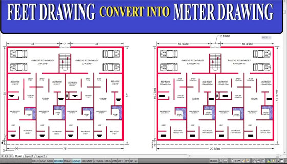
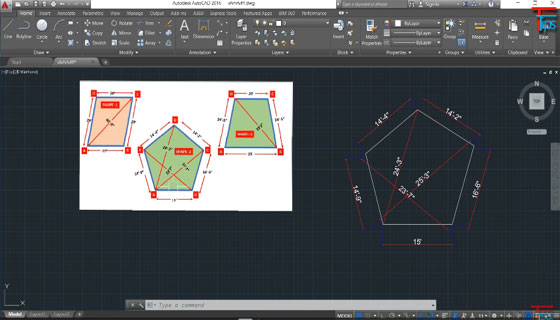
In this AutoCAD video tutorial, you will be familiar with some useful steps to create the design of any irregular shapes in AutoCAD.

By watching this tutorial, you will be able to draw any irregular shape devoid of knowing the angle of that object.

The best way is to draw the diagonal then apply intersecting circles which are drawn from the endpoints.

Area belongs to a property of AcDbPolyline. If you transform your entities to polylines, then join them with the pedit command to recover the area with the list command or via lisp.

It is not necessar to join them. Just type "area" at the command line and start selecting points, but you must close the area or it won't be perfect.

To learn the detail methods, go through the following AutoCAD video tutorial.

Video SourceTutorials Tips

How to design irregular shape in AutoCAD

~~~~~~~~~~~~~~~~~~~~~~~~
Published By
Rajib Dey
www.bimoutsourcing.com
~~~~~~~~~~~~~~~~~~~~~~~~


Thursday, December 27, 2018

Learn to generate surface profile from file in AutoCAD Civil 3D

In this exclusive autocad tutorial, you will learn how to generate surface profile of existing road from file in AutoCAD Civil 3D. The surface will be created directly based on the labels and profiles. You don’t to draw surface separately. Initially, it is required to generate profile from file.

It is possible to generate a surface profile either from a horizontal alignment on a surface or from a surface profile file.

While generating a centerline profile, just produce one or more offset profiles simultaneously. Employ the Draw in Profile View option to illustrate the profile in the drawing.

Click Home tab > Create Design panel > Profile drop-down > Create Surface Profile Find.

In the Create Profile from Surface dialog box, in the Alignment list, choose the horizontal alignment to be utilized for the profile.

Make sure, that the surface to be utilized should be listed in the select surfaces list. If several surfaces are listed, apply Ctrl + click to choose one or more of them from which the profiles will be formed.

Optionally, in the Station Range area, indicate start and end stations if it is necessary for the profile to cover a distance under the entire length of the horizontal alignment.

Click Add to add the centerline profile to the Profile List.

Optionally, choose the Sample Offsets check box. Put the offset distances in the field if it is required for the profile to comprise one or more offsets from the centerline of the horizontal alignment. Apply positive numbers to indicate exact offsets, and negative numbers for left offsets. It is recommended to utilize commas to detach the values. As for instance : 20,-20,30,40.

Optionally, click Add to add the offset profiles to the Profile List.

In the table, to make analysis of the data for each profile line and make modifications when necessary.

Optionally, add or delete profiles in the Profile list.

Optionally, choose the Sample Offsets check box. Put the offset distances in the field if it is required for the profile to comprise one or more offsets from the centerline of the horizontal alignment. Apply positive numbers to indicate exact offsets, and negative numbers for left offsets. It is recommended to utilize commas to detach the values. As for instance : 20,-20,30,40.

In the table, to make analysis of the data for each profile line and make modifications when necessary. Optionally, add or delete profiles in the Profile list.

Perform one of the following:

If it is required to draw the profile in a profile view, click Draw In Profile View, and then opt for the create profile view method.

Click OK. The generated profiles are saved. If the alignment contains one or more profile views connected with it, the generated profiles are attached to the views.

Learn to generate surface profile from file in AutoCAD Civil 3D

Read more


~~~~~~~~~~~~~~~~~~~~~~~~
Published By
Rajib Dey
www.bimoutsourcing.com
~~~~~~~~~~~~~~~~~~~~~~~~

Monday, December 24, 2018

Different types of risks with BIM (Building Information Modeling)

Building information modeling (BIM) software is a tool that can be used to minimize the cost of construction as well as accelerate the construction process of any project.

BIM software can decompose components of the job and help to obtain a superior understanding of the construction project that is executed by the contractors and subcontractors. If employed perfectly, BIM can minimize construction time, costs, and claims.

The problems may occur when BIM is not precisely shared and demonstrated to all construction members.

Communication: While enforcing BIM as an inherent part of your project, the problem may arise if proper collaboration is not made among everyone associated all through the construction phases. With BIM, the architects can produce a superior building model that minimizes costs and materials, if the general contractor (GC) is not involved on the plan, then claims and issues will take place.

Control: As soon as the BIM is formed and allocated to the project members, proper protection should be taken to minimize the scope for consequent modifications by unauthorized parties. The process is complicated to modify a BIM model on large construction projects where various consultants and contractors give effort to complete modifications to reap their own advantage devoid of distributing the ideas to the whole group. Hence, a team leader should be appointed and performed as the only authorized user to rectify the BIM model.

Design Errors: Who will be responsible when the building collapses to abide by the most updated construction codes? There exist a thin line among liabilities as each party taking part in planning phases, corrections and input to the BIM model. In several cases, legal issues are stimulated by claims demonstrated by the GC, because of misinterpretation or inappropriate designs. Due to these types of errors, extra legal fees may incur which were not taken into consideration in the original contract, minimizing the savings formed with the BIM process.

Construction Costs: When BIM is employed on construction projects, it provides an idea of the total anticipated construction costs without showing the real cost. BIM facilitates you to work out the most precise building cost-to-complete, but it will not take into account actual price deviation from developing market like metals and petroleum-derivative products, politically-vulnerable commodities like oil, and uncontrollable events like natural disasters.

Minimizing Errors - The following tips are important for eliminating some errors and risks common to using BIM:

• The BIM team leader should be a tech-savy.

• BIM group members should have the capacity to communicate their ideas smoothly.

• Liabilities should be allotted evidently. Each team member should be well versed with their role and drawbacks.

• Make sure your contractors can build with BIM.

• Consult with your insurance agent regarding all relevant issues that can develop from malpractice issues and under-performing relevant issues.

• Apply clear and specific contracts that can recognize all potential risks and their liabilities.

Next Steps: BIM is applied with the Integrated Project Delivery system to curtail claims and possible issues. Some key specific legal clauses can also be integrated into the construction and design contracts. As with BIM, better communication among team members is the most vital factor to get success while employing BIM-IPD in your construction project.

Read more

Different types of risks with BIM (Building Information Modeling)

~~~~~~~~~~~~~~~~~~~~~~~~
Published By
Rajib Dey
www.bimoutsourcing.com
~~~~~~~~~~~~~~~~~~~~~~~~

Thursday, December 20, 2018

A position is vacant for designer with Revit experience in USA

Alex Pettas Architecture (APA), a California based young, design-oriented architecture firm, is seeking a skilled and motivated designer to offer an integral role in the design and production of projects ranging from concept through construction with Revit.

QUALIFICATIONS - SKILLS - REQUIREMENTS

a. 2+ years of working experience in an architecture firm.
b. A degree from an recognized architecture program.
c. Revit experience is necessary; sound knowledge in Adobe CC.
d. Outstanding design and problem-solving skills.
e. Ability to independently deal with several assignments.
f. Should have sound verbal and written communication skills.
g. Attention to detail and diligence are essential.
h. Study and ensure code compliance; experience guiding LADBS authorizing process.
i. Experience coordinating consultant work.
j. Research on finish materials and products.
k. Inhabitant of Los Angeles area with the capacity to work legally in the U.S.

BENEFITS

A competitive salary, paid time off, sick leave, health insurance benefits, bonuses and support for IDP and ARE exams. Besides, get bonus days off throughout the year-end holidays.

CONTACT

To apply for the post, send your resume and portfolio to info@pettas.com. Mention availability to start and your level of experience with Revit. Attachments should not be in excess of 15 MB.

A position is vacant for designer with Revit experience in USA

~~~~~~~~~~~~~~~~~~~~~~~~
Published By
Rajib Dey
www.bimoutsourcing.com
~~~~~~~~~~~~~~~~~~~~~~~~

Tuesday, December 18, 2018

An exclusive tutorial on rooms in Revit

In this exclusive revit tutorial, you will get details about rooms in Revit like location of rooms in your projects, how the rooms can be presented in a superior way with colors, how the information can be pulled out from your model to obtain information (area, perimeter, finishes etc.) concerning your rooms.


Get some useful notes on rooms in Revit :-
Open a plan view and apply the Room tool to arrange rooms in the building model.
Automatically set rooms in all closed and bounded areas on the current level.
By default, rooms are never demonstrated in plan views and section views. However, it is possible to modify the visibility/graphic settings to generate rooms and their reference lines observable in these views.

It is possible to copy rooms from one phase to the next to retain their properties.
In order to allocate information regarding the rooms and spaces in a model, an architect and a mechanical engineer have to utilize linked models or worksharing.
Revit employs room boundaries while measuring the area, perimeter, and volume of a room.
Revit can work out the area and volume of rooms and demonstrate the information in schedules and tags.

To get more details, go through the following Revit video tutorial.

Video Source: Balkan Architect

An exclusive tutorial on rooms in Revit

~~~~~~~~~~~~~~~~~~~~~~~~
Published By
Rajib Dey
www.bimoutsourcing.com
~~~~~~~~~~~~~~~~~~~~~~~~

Friday, December 14, 2018

How to convert the measuring unit of a drawing from feet/inches to meter in AutoCAD

This AutoCAD tutorial is specifically designed for beginner’s AutoCAD users. In this tutorial, one will learn how to convert the drawings which were produced with measuring units feet and inches to the measuring unit meter.

In this tutorial, some useful AutoCAD commands like Units command (short form UN), Insert command (short form I), Dimension Style (short form D), Linear command (short form DIM) and Match command (short form MA).

Units command – The purpose of this command is to control the accuracy and display formats for coordinates, distances, and angles and save them in the existing drawing.

Insert command – This command is used to insert a block or drawing into the existing drawing.

Dimension Style – This command is utilized to generate new styles, fix the current style, rectify styles, set overrides on the existing style, and compare styles.

Linear Command – It is applied to generate several types of dimensions inside a single command session.

Match Command – It is utilized to copy properties of one object to another maintain full control over properties copied.

To learn the tricks for converting the drawing’s measuring units feet & inches to meter, go through the following video tutorial.

How to convert the measuring unit of a drawing from feet/inches to meter in AutoCAD

Read more
~~~~~~~~~~~~~~~~~~~~~~~~
Published By
Rajib Dey
www.bimoutsourcing.com
~~~~~~~~~~~~~~~~~~~~~~~~

Wednesday, December 12, 2018

IMAGINiT Technologies introduced IMAGINiT Clarity for Revit 2019

IMAGINiT Technologies launched 2019 IMAGINiT Clarity Family of Products which provide a new scope for the Revit users to avail and control the model data of Revit efficiently.

There is a new dashboard and incorporation with Autodesk Dynamo facilitates the BIM professionals to obtain over 55 metrics across several projects allowing collaboration among project partners.

The followings are some new and advanced features of the product :-

MAGINiT Clarity now supports Revit 2019 and earlier versions of Autodesk Revit, as well as BIM 360 software.

A New High-Level Dashboard facilitates the BIM coordinators to observe significant data on one screen to recognize and deal with the issues instantly. On the dashboard, user-defined ranges make out issues in red and yellow facilitating BIM Coordinators to easily check trends across several models and projects and tackle any variations.

Clarity/Dynamo Integration applies bespoke Dynamo nodes to obtain model metrics that are not presently in IMAGINiT’s list of 55 metrics and pulls them into the Clarity 2019 dashboard. With bespoke Dynamo scripting, the users will be able to directly access the metrics on the opening page of the Revit model.

Integration with BIM 360 allows flexibility to project partners by providing every team a specified area to preserve their updates to the model. Teams can then take decision whether they prefer to pull in work from other project partners or distribute their work with them on the basis of important milestones.

Additional Task Management improvements like the capacity to print a hard copy and new integration with SharePoint simplify the Clarity environment and make the application simple for BIM team members.

To get more details, visit www.imaginit.com/clarity

IMAGINiT Technologies introduced IMAGINiT Clarity for Revit 2019

~~~~~~~~~~~~~~~~~~~~~~~~
Published By
Rajib Dey
www.bimoutsourcing.com
~~~~~~~~~~~~~~~~~~~~~~~~

Friday, December 7, 2018

The role of BIM and FM in existing building

The latest digital tools are applied to perfectly capture wide-ranging 3D point cloud data as well as record the built environment with amazing detail and perfectness, irrespective of the nature or use of the building.

The objective of point clouds and high resolution, high dynamic ranging imagery data sets is to support drafting and modelling tasks, an office supported method that facilitates the formation of dependable and genuine digital copies of reality.


In due course, these intelligent, parametric models framework the optimum way for distributing the project and asset information, substituting the conventional 2D computer aided design drawings.

Besides, the BIM output is customized to make it suitable for the owners and operators: populating BIM objects with asset information whereas connecting these objects with Facilities Management software, facilitates the application of the model throughout the operation of the facility and getting advantage from inclusive 3D spatial illustrations of the assets.

In reality, surveying and modeling as built structures and assets can put challenges: a common barrier is the scarcity of comprehensive asset registries. All through as-built surveys the asset should recognized and coordinated with the survey data set; a prospective method is to label prevailing assets with unique ID’s or employ RFID’s to recognize each pertinent object, as a consequence rendering them assignable inside the survey data set.

Predefined attributes allotted to parts or components in a BIM package can be expanded to adapt specific requirements like part numbers, model or product codes can be added in shared parameters that extend the predefined inventory. In the same way, elements like installation date or warranty expiry date, pertinent for operation and management, can be included with the BIM.

The movement of data among BIM and FM software is more and more streamlined with the use of the COBie (Construction Operations Building Information Exchange) data format. This non-proprietary format set ups a standard for the publication and delivery of asset data and is compatible with the more suitable BIM and FM packages. By generating scripts to automate the flow of data among different tools is the most recognized method of systematically updating and retaining the models and asset registries devoid of manual data entry.

Implementing BIM is a process to consolidate digital information, removing redundancy and thus arranging more and accurate data for FM tasks. It makes sure that the models accessible online will provide lots of advantages to maintenance works. As a result, the service engineer can apparently trace the components for maintenance purpose and verify the work order as soon as the item is recognized. Upon completion of the servicing work, the same technician can populate the appropriate object parameters, thus computerizing the system of updating the central model and FM database.
Article Sourcewww.bimireland.ie


~~~~~~~~~~~~~~~~~~~~~~~~
Published By
Rajib Dey
www.bimoutsourcing.com
~~~~~~~~~~~~~~~~~~~~~~~~

Wednesday, December 5, 2018

How to efficiently utilize design options in Revit

In this exclusive Revit video tutorial, you will learn how to apply the stunning design options tool in Revit to explore through various design options and use them in your 3d model. Test these design options and check how they perform devoid of saving individual files.


The users can access design options in the following two ways :-
From the Manage tab > Design Options (under Design Option Panel).

At the bottom bar of the Revit window, click the icon.
When the Design Options dialog box open, it is found that the dialog box is segregated into 2 parts. The white box on the left shows all the design options available for any project. In the right side, there are the editing tools like Edit, Option Set and Option which are utilized to produce the design options.
Edit – This option allows you to edit each option. There is another option alias Switch between Options to edit option quickly.
Option Set – It is a folder that retains all the options for a specific area of interest. As for example, one Option Set for “Office Suite” and another Option Set for “Cafeteria”.
Option – These are the options produced inside the Option Set. As for instance, inside the “Office Suite” set, there is Option A, B & C furniture layout design.

Note: There are numerous Option Set in the same view, but each view can only contain one Option.
Setting up Design Option
Initially, it is required to setup all the Option Sets and Options required, then assign the components in the existing model to the exact option. An analogy is to setup folder and blank files as a place holder primarily, then include components to the blank file later.
Step 1: Under Option Set, click “New”, it will generate first set of Design Options.
Step 2: Under Option, click “New”, it will generate first design option in the set. It is possible to produce as many Option as required within the equivalent set.
Note: Revit will not permit the users to make an Option unless an Option Set is made.
Reiterate the above steps as required to generate more Option Set and Options.
The Option with the word (primary) next to it is known as Primary Option. This is the default design that shows in your model. The users can choose any option as the Primary by clicking Make Primary (under Option).
To get more clear ideas, go through the following video tutorial.
How to efficiently utilize design options in Revit
~~~~~~~~~~~~~~~~~~~~~~~~
Published By
Rajib Dey
www.bimoutsourcing.com
~~~~~~~~~~~~~~~~~~~~~~~~

Tuesday, December 4, 2018

New 2019 versions of AutoCAD for the Apple macOS platform are launched by Autodesk

This release offers AutoCAD for Mac for the German-language markets (DACH countries) and Japan. As soon as the app is set up, just choose your desired language from the Application Preferences dialog and restart AutoCAD for Mac.

Given below, some exciting features of AutoCAD 2019 for Mac
New DWG Compare Feature

The new DWG Compare feature in AutoCAD 2019 for Mac and AutoCAD LT 2019 for Mac facilitates the users to efficiently recognize the graphical differentiation among two revisions of the similar drawing or Xref.
Now, the users will be able to view significant variations, recognize clashes, and review constructability and more. If revision clouds feature is activated, it will further focus on the alterations and it is possible to run through each change to ensure that each new change is updated.
Purge Multiple Objects
This option allows to purge numerous objects immediately. A new user interface for the Purge command is included to purge numerous types of objects simultaneously. By default, all named items are chosen for purging.
The newest Purge improvements are simple and user-friendly.

Efficiency Plot with New Plot Preview
The Plot Preview dialog is also significantly modified. The more frequently used options are now placed at the top for easy availability. With the new layout view, it is now possible to view how your layout will look post-plot and change settings to reflect the changes in real time.
Create Views While Designing—NEWVIEW Command

With a new Views and Viewport feature, the users will be able to produce views at the time of designing, then rapidly include any of the saved views in a layout in paper space. The NEWVIEW command generates a named view from what’s demonstrated in the current viewport, or from a rectangular window already settled.
With new View Gallery, the user can insert a named view from the toolbar. Thus a view in paper space can be created quickly and the time is saved for modifying the view by zooming in and out.
Define Default Layer for Xrefs
A new XREFLAYER system variable facilitates the users to indicate a default layer on which new Xrefs are included, saving the user from having to modify the Xref’s layer after inclusion of each. To ease the process to view which Xref layers contain overrides, a new Xref Overrides layer filter is automatically generated once the overrides are employed.

New 2019 versions of AutoCAD for the Apple macOS platform are launched by Autodesk

~~~~~~~~~~~~~~~~~~~~~~~~
Published By
Rajib Dey
www.bimoutsourcing.com
~~~~~~~~~~~~~~~~~~~~~~~~

Saturday, December 1, 2018

Some useful AutoCAD tips to generate a simple floor plan

In this exclusive AutoCAD video tutorial, you will learn how to generate a simple 2D floor plan in AutoCAD based on given plan and requirements.

In this video, one 1 BHK 2D plan is developed in AutoCAD.

A 2D floor plan stands for a type of diagram that demonstrates the layout of a property or space from above. It will often illustrate the walls and room layout, along with fixed installations like windows, doors, and stairs as well as furniture. 2D signifies that the floor plan is a “flat” drawing, without perspective or depth.

There is a square shape land with dimension 20 feet x 20 feet and the plan will be developed for this land.

To draw anything in AutoCAD, the following two rules should be followed :-

Rule 1 : Right hand should always remain on the mouse.
Rule 2 : Left hand should always remain on the keyboard.

Prior to start drawing in AutoCAD, units and limits should be set perfectly.
If your drawing is created with the measuring unit feet and inches, the unit should set as architectural.
If your drawing is created with the measuring unit millimeter or centimeter, the unit should set as decimal.

The command for unit is given as UN and for limit is given as LIMITS. After pressing enter, the lower left corner should be 0,0.
To learn the complete process, go through the following video tutorial.
Some useful AutoCAD tips to generate a simple floor plan
~~~~~~~~~~~~~~~~~~~~~~~~
Published By
Rajib Dey
www.bimoutsourcing.com
~~~~~~~~~~~~~~~~~~~~~~~~

Friday, November 30, 2018

Some useful tips to draw front elevation in AutoCAD

In this autocad video tutorial, you will learn some useful tips to draw front elevation of any building.

Once a elevation line is drawn, it is necessary to extract an elevation from the elevation line and the objects picked up in the building model.

As soon as a 2D elevation is created, the object produced is a 2D Section/Elevation object. Both 2D sections and elevations contain the equivalent object type and style.

Prior to generate an elevation, thaw and activate all layers of objects in the building model that should be contained in the elevation. The Objects on layers which are off or frozen cannot be segment of the selection set for the elevation. To make the performance better, deactivate the layers of the objects that should not be contained in the elevation.

2D Elevations: 2D elevations are produced by drawing an elevation line in front of a number of objects and then generating a 2D elevation object out of them. The elevation object is drawn devoid of hidden and overlapping lines.

It is possible to edit a 2D elevation by modifying its object display properties or its style display properties. The 2D elevation style facilitates the users to include display components to the display illustration of the elevation and develop rules that assign various parts of the elevation to several display elements.

The visibility, layer, color, linetype, lineweight, and linetype scale of every elements can be easily managed. It is also possible to assign a material like a brick or concrete hatch, to individual components of the object or the style. Furthermore, you can use linework editing commands to assign lines in a 2D elevation to several display elements, and combine geometry into a 2D elevation. The users can dimension 2D elevations.

3D Elevations: 3D elevations are produced by drawing an elevation line in front of a number of objects and then generating a 3D isometric elevation object out of them. The styles are not employed in 3D elevations.

The display of subdivisions inside 3D elevations can be managed easily. With the use of the Hidden Line Projection command, the users can generate 2D hidden line projections of any view of the 3D elevation that can be exploded and edited or hatched.

To learn the tricks to draw front elevations in AutoCAD easily, go through the following video tutorial.

Some useful tips to draw front elevation in AutoCAD

Read more
~~~~~~~~~~~~~~~~~~~~~~~~
Published By
Rajib Dey
www.bimoutsourcing.com
~~~~~~~~~~~~~~~~~~~~~~~~

Monday, November 26, 2018

SOFiSTiK Bridge Modeler – A robust software to apply BIM in bridge design & modeling

Sofistik, the leading software developer, has launched SOFiSTiK Bridge Modeler that can be used to develop parametric bridge models with alignment parameters.

It is user-friendly tool for bridge planners all through the globe. The software produces completely parametric input and semi-automated, adaptable plan creation, simplifying the process to analyse several design variants.

With SOFiSTiK, it becomes easier to obtain step-by-step complicated geometries based on the smallest detail. It can be performed by first selecting one or more axes from the road planner or by specifying the axes out of horizontal or vertical layout information. Then the required bridge cross-section is chosen from the adjustable cross-section families the software offers.

The Bridge Modeler contains advanced modeling capabilities and parameterization of the whole structure to make simple and easy analysis of numerous variants along with the computation of dimensions and costs.

The model is utilized to automatically create cross-sections with pre-dimensioned views and sections. These and other user-generated views or lists are also automatically modified with regard to modifications to the model.

The users can also produce a developed section cut of the model in Revit and add tags to it.

The software supports BIM in Bridge Design and Detailing. The users can produce parametrized 3D bridge models with alignment parameters and generic families in Autodesk® Revit® 2019.

To get more details about the software, go through the following link www.sofistik.com

SOFiSTiK Bridge Modeler – A robust software to apply BIM in bridge design & modeling
~~~~~~~~~~~~~~~~~~~~~~~~
Published By
Rajib Dey
www.bimoutsourcing.com
~~~~~~~~~~~~~~~~~~~~~~~~

Saturday, November 24, 2018

A position is vacant for Revit Designer in US locations

Alex Pettas Architecture is a three-year old architecture firm based at Los Angeles just east side of Culver City in CA and currently they are working on residential projects in Bentwood, the Hollywood Hills, San Francisco and Sonoma County as well as retail projects. Their aesthetic is rooted in California modernism.

Currently they have urgent need for a highly stimulated Designer for playing an essential role in the design and production of projects from concept through Construction using Revit.

They are looking for a candidate who is immensely passionate and dedicated about architecture, has a strong work experience and also enthusiastic to play a vital role to their projects while handling them carefully. They belong to an office culture which is creative, communicative and collaborative.

Qualification, Skills and Requirements:

• Applicants must have an experience of 1-4 years in an architecture firm.
• A degree from an authorized architecture program is a must have thing.
• Revit experience with proficiency in Adobe CC is needed.
• A candidate should be self-starter who will able to manage multiple assignments.
• He or she should be strong enough in communication like gin graphic, written and verbal.
• Candidate should be attentive to little details and go for thorough process.


Technology Experience and Expertize:

• Candidate must examine agency needs, ensure code compliance and control permitting process.
• Research finish materials and products.
• Have to flexible enough to handle clients and attend project site meetings.
• Candidates who live around Log Angeles have to be the legal work ability in the U.S.


Benefits: They are offering a competitive salary, paid time off, health insurance benefits, bonuses and ARE exam subsidies; there will be also bonus day off during the year-end holidays. But they don’t sponsor H1b applicants.

Contact info: Interested person can email their resume and portfolio to info@pettas.com. Attachments should be no longer than 15 MB.

Apply now: archinect.com

A position is vacant for Revit Designer in US locations

~~~~~~~~~~~~~~~~~~~~~~~~
Published By
Rajib Dey
www.bimoutsourcing.com
~~~~~~~~~~~~~~~~~~~~~~~~

Monday, November 19, 2018

A position is vacant for BIM analyst in US locations

BLDGWORKS, a growing construction integration, real estate development, and architecture firm, is inviting applications for the position of a BIM analyst on full time basis for the locations of New York, NY, US.

The objective of BIM Analyst is to employ virtual projects controls with a large corporate client involved in a large portfolio of work around the world. The BIM Analyst has to make design and construction of Building Information Models to facilitate QTO and cost analysis.

This role provides the scope toward any member of the Architect / Engineer / Construction community with an interest in BIM (3D,4D,5D modeling) to fully employ and delve into these methods of documentation.


Academic Experience:
• Degree in architecture, engineering, construction, project controls, or related fields required
• 0-3 years experience with BIM platforms (mainly Revit)
• Interest in project controls, QTO, and cost analysis
• Exhibition of leadership skills
• Capability to think innovatively and strategically to provide solutions
Technology Experience and Expertize:

• Experience with Revit highly desired
• Experience with Rhino preferred but not essential
• Experience with Dynamo will give added advantage but not essential
• Experience with Python scripting will give added advantage but not necessary
• Experience with Revit API will give added advantage but not essential
• Salary structure will be equivalent to experience.
• Contribution to healthcare
• Paid Time Off
BLDGWORKS inspires the employees to perform towards NCARB licensure, AIA membership, and other certifications like LEED. If any candidate possesses any such licenses and certifications, he/she will get special consideration.
Prospective candidates should send a cover letter, resume, and portfolio along with salary requirements to office@bldg-works.com
A position is vacant for BIM analyst in US locations
~~~~~~~~~~~~~~~~~~~~~~~~
Published By
Rajib Dey
www.bimoutsourcing.com
~~~~~~~~~~~~~~~~~~~~~~~~

Saturday, November 17, 2018

How AutoCAD is used for drawing column layout plan

Fundamentally, column layout plan is drawn with hand or AutoCAD. Given below, some useful step-by-step guidelines for column layout drawing with AutoCAD.

The following steps are involved :-


1. Select Column Shape: Initially, select the column shape. Several types of column shape are applied in diverse structures which range from circular, rectangular, box type column. Hence, it is important to select the column shape beforehand.
2. Draw the Column: As soon as the column shape is selected, then draw the column by applying the commands as rectangle (rec+Enter) or circle(c+Enter).
3. Settle the Column Location: Placement of column is considered as the most crucial part of a structure. The construction of a structure is based on the location of the column. Therefore, all the columns should be arranged at the exact location.
4. Settle the Grid Line: Gridline is a very significant segment of a structure since the position of all sections of the structure is set based on the grid line. The grid line should be drawn (horizontal & vertical) with line (l+Enter) or construction line (xl+Enter) command.
5. Numbering the Grid Line: The grid line should be numbered with a, b, c or 1,2,3 serially. It facilitates to trace something quickly and effectively.
6. Settle the Dimension with regard to Grid Line: Settle a dimension of all column relating to grid line with dim leaner (diml+Enter) command as except dimension it becomes complicated to trace the position of the column.
7. Numbering the Column: Locate a column to check that the schedule is not possible devoid of proper numbering. Therefore, the column should be numbered depending on its size & reinforcement.

How AutoCAD is used for drawing column layout plan
~~~~~~~~~~~~~~~~~~~~~~~~
Published By
Rajib Dey
www.bimoutsourcing.com
~~~~~~~~~~~~~~~~~~~~~~~~