adsense analytic

Showing posts with label Tutorials. Show all posts

Friday, March 27, 2020

Some exciting features of Revit 2020

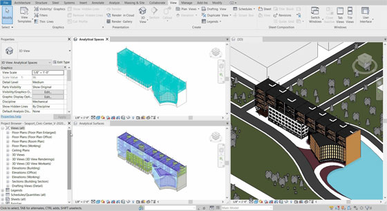
In this article, detail information is given on some exciting features in Revit 2020.

1. NEW PATH OF TRAVEL TOOL: The new Path of Travel feature facilitates to choose a “start point” and an “end point”. Revit will then automatically work out the shortest path among the two points i.e. it now circumvents walls and attempt to locate doors.

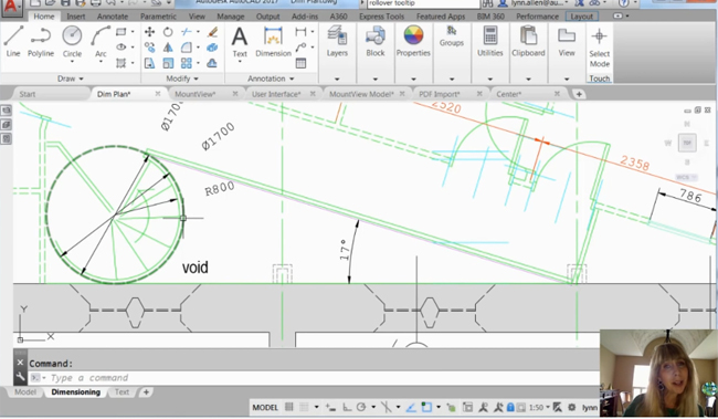
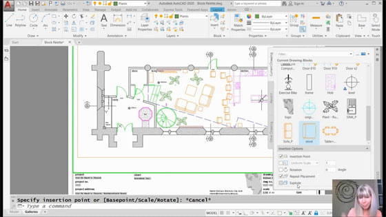
2. IMPORT PDF TO REVIT: Visit the Insert tab in the ribbon to get a brand new Import PDF tool.

When the PDF includes vector lines, the Enable Snap feature can be applied to interact with the lines with tools like “pick lines”.

As soon as the snaps are enabled, the “pick walls” tool can be applied to employ the PDF as a reference to generate new walls and other model elements.

3. MAKE ELLIPTICAL WALLS: The elliptical wall feature is now directly incorporated with Revit.

4. EDIT SCOPE BOXES IN VIEW LIST: It is now possible to include the “Scope box” parameter in a “view list” schedule i.e. instantly assign scope boxes devoid of inputting a view manually. It is ideal for projects with a plenty of views. Ensure to add the “Scope Box” parameter in the fields of the view list.

Some vital tips for beginners users of BIM

~~~~~~~~~~~~~~~~~~~~~~~~
Published By
Rajib Dey
www.bimoutsourcing.com
~~~~~~~~~~~~~~~~~~~~~~~~

Friday, January 10, 2020

How To Customize Your AutoCAD Tooltips

Lynn Allen, the renowned Autodesk Evangelist, who is associated with Cadalyst Magazine, provides some handy tips on how to control the timing of AutoCAD’s tooltips as well as customize them as per your requirements.
 
By watching this AutoCAD video, one will get solution for turning off the tool tips/pop ups while entering a command.
 
Dynamic tooltips offer an alternate process to enter commands. Once dynamic input is turned on, a tooltip demonstrates dynamically updated information adjacent to the cursor. When a command is ongoing, it is possible to identify options and values in the tooltip text box.

Read more
How to customize your AutoCAD Tooltips

~~~~~~~~~~~~~~~~~~~~~~~~
Published By
Rajib Dey
www.bimoutsourcing.com
~~~~~~~~~~~~~~~~~~~~~~~~

Tuesday, October 15, 2019

Download Various 2D Drawing House Plans At Free Of Cost

Explore through an extensive lists of AutoCAD plans along with 3d models and 2D CAD drawings. All these can be downloaded at free of cost.
The list includes house plans, structural plans, concrete blocks, garage plans etc. All the plans are available in .dwg formats.
These house plans are very useful for civil and structural engineers to produce initial designs for sturctures and find out errors prior to production. It will save huge time and resources for them.
One can access these plans from the following link onlinecivilforum.com
Download various 2D drawing house plans at free of cost
~~~~~~~~~~~~~~~~~~~~~~~~
Published By
Rajib Dey
www.bimoutsourcing.com
~~~~~~~~~~~~~~~~~~~~~~~~

Monday, October 14, 2019

Some Useful Tips On Autocad User Interface

The following autocad article provides some useful autocad tips to maintain the standard workspace.
Tricks for AutoCAD user interface - Learn how to deactivate the ribbon and produce a minimum workspace:
1. Give command RIBBONCLOSE
2. Give command MENUBAR 1
3. Select the Tools menu > Toolbars > AutoCAD > Layers
4. Select the Tools menu > Toolbars > AutoCAD > Properties
5. Lots other can be included as per requirements
6. Dock the toolbars at the top of the drawing area
7. Give command MENUBAR 0
8. Click the Workspace button and Save Current As ..., label it “Minimal” or whatever

Some useful tips on Autocad user interface
~~~~~~~~~~~~~~~~~~~~~~~~
Published By
Rajib Dey
www.bimoutsourcing.com
~~~~~~~~~~~~~~~~~~~~~~~~

Saturday, October 12, 2019

Download 1000+ AutoCAD Plans

Given below an extensive lists of autocad plans. The lists consist of near about 1000 modern house autocad plans which can be downloaded easily.
 
These plans contain floor plan, sections, elevations , electric detail and working plan of house. These plans will be useful for the architects and interior designers.
 
These plans are available in .dwg formats. These plans will facilitate the architects to instantly and efficiently draw walls as well as doors and windows.

Read more

Download 1000+ AutoCAD plans

~~~~~~~~~~~~~~~~~~~~~~~~
Published By
Rajib Dey
www.bimoutsourcing.com
~~~~~~~~~~~~~~~~~~~~~~~~

Monday, September 30, 2019

Directly model from laser scans to Revit with InfiPoints Revit Plug-in

Elysium has introduced an advanced functionality to model piping and structures from 3D laser scanned point clouds into Autodesk Revit.
With this feature, the Revit users will be able to minimize their modeling time significantly.
Recently 3D laser scanners are extensively used to capture the on-site environment more completely and precisely. But subsequent modeling of the environment devoid of the proper point cloud software requires huge labor and time.
InfiPoints can automatically draw out the pipes and planes from point cloud data captured from 3D laser scanners. The users then get the ability to generate CAD models with simple clicks of mouse.

Directly model from laser scans to Revit with InfiPoints Revit Plug-in
~~~~~~~~~~~~~~~~~~~~~~~~
Published By
Rajib Dey
www.bimoutsourcing.com
~~~~~~~~~~~~~~~~~~~~~~~~

Thursday, August 29, 2019

Details of Autodesk Revit 2020.1 Update

Autodesk recently introduced the Revit 2020.1 Update that can be accessed via the Autodesk Desktop App or via download from the Autodesk subscription site.
Revit Updates can’t be uninstalled to get back to Autodesk Revit 2020 to its pre-update state. If it is required to eliminate the update, uninstall Autodesk Revit 2020 and then reinstall it.

Given below, some exclusive features of Revit 2020.1 Update.
MEP Systems Analysis: The most exciting features is the inclusion of totally new MEP systems analysis functionality combining with OpenStudio to facilitate custom workflows. The customization varies from local code compliance to integrating certain manufacturer equipment, incorporating analytical to physical modeling together.
At a high level, within Revit, this new feature is suitable for establishing an entire system devoid of modeling any MEP elements.

Banding in Schedules: In schedule views, click on the new Stripe Rows toggle on the Ribbon to illustrate shading in every other row. It does not become visible to show up on sheets or print.
Attach Walls Dialog: The "attach walls" dialog is rectified to make the current selection as the default. To modify, or nullify this, it is required to edit the Revit.ini file.
Path of Travel Tool Updates: The new-to-Revit-2020 Path of Travel tool is totally upgraded. The start and end points are dragged, resulting to an automatic update. The To Room and From Room parameters are shown in schedules and tags. Finally, now there will be a Reveal Obstacles toggle on the Analyze tab.
Site Points observable in Links: The Project Base Point and/or Survey Point from the linked models are now visible inside the host. When the point is shown, and the link is chosen, the point "lights up" and also lists are location data!
Details of Autodesk Revit 2020.1 Update
~~~~~~~~~~~~~~~~~~~~~~~~
Published By
Rajib Dey
www.bimoutsourcing.com
~~~~~~~~~~~~~~~~~~~~~~~~

Saturday, August 24, 2019

Prota Structure 2019 for designing 15 Storied Building

In this video tutorial, you will get step-by-step guidelines for designing a 15-storied building with the use of Pro Structure 2019 software. You will gather knowledge on replicate/generate story, cantilever slab with loading, story with wall load editing etc.
The software is very useful for multi-component modeling and provides complete support for handling steel and concrete structures along with the support for finite element analysis.
The application offers proper solution for handling the construction structures and composite sections together with detailing features and a lot more. The application offers non-linear element transitions and seismic assessment and retrofitting features. Besides, it is very effective for producing the structural designs, customizations and component design management for the design professionals and the engineers.
By utilizing its rapid modeling capabilities, the users will be able to save a significant time and provides support for analytical methods or FE for grouping. This powerful application offers a complete solution toward component design management for the engineers. It can deal with the steel, concrete and composite sections designing with 3D finite element analysis features.

The software offers the following exclusive features :-
• Robust application for multi-component modeling
• Compatible with concrete and steel structures
• Manage composite sections and supports finite element analysis
• An advanced set of tools for scene construction and non-linear analysis
• Seismic review and retrofitting features
• Manage the insulation and dedicated system for structural design
• Customize the designs as per requirements
• Consistent solution for Engineers and design professional
• Design management features and various non-linear element analysis
• Create structural designs and customize the designs accordingly
• Frame structure systems and handle floors and system bases
• Apply analytical methods for FE grouping
• 3D finite element analysis with visual results and precision
• A cost-effective solution with different customizations
• Various other powerful options and features
For online demonstration, go through the following video tutorial.
Prota Structure 2019 for designing 15 Storied Building
~~~~~~~~~~~~~~~~~~~~~~~~
Published By
Rajib Dey
www.bimoutsourcing.com
~~~~~~~~~~~~~~~~~~~~~~~~

Monday, August 12, 2019

Newest Trezi 1.8, a VR product compatible with Revit & Sketchup

Trezi 1.8 is the newest version of Virtual Reality (VR) product for the building industry. It offers an improved virtual collaboration system that is well suited with leading architecture design software like Sketchup, Rhino, and Autodesk’s Revit.
Trezi significantly changes design communication, and collaboration in the building industry by facilitating the stakeholders to meet the project’s design at full-scale.
Architects and interior designers employ Trezi to convert their current 3D design models into a completely immersive VR environment. It has minimized errors and omissions and nominal material wastage in prototyping and on-site experimentation reduces the requirement for laborious personal meetings and site visits, Trezi puts a new dimension to the understanding, communication and translation of design in the industry.
Trezi 1.8 keeps the fully immersive virtual experience a few steps higher with its new collaboration feature that facilitates the architects/designers to fulfill and involve colleagues and collaborators in the virtual world.
Regardless of their geographical location, architects and interior designers can walk around a true-to-scale rendition of their building or interior design and create edits in real-time, if necessary.
Trezi 1.8 also offers an exterior rendering mode that considerably enhances the rendering quality of exterior scenes as well as photo-realistic shadows, multi-source illumination, and minimal culling of objects from the scene.
With greater support for remote collaboration and audio add-ons in the pipeline, Trezi 1.8 sets out to radically enhance and raise the bar for design-based collaboration in the industry.
To get more details, go through trezi.com
Newest Trezi 1.8, a VR product compatible with Revit & Sketchup
~~~~~~~~~~~~~~~~~~~~~~~~
Published By
Rajib Dey
www.bimoutsourcing.com
~~~~~~~~~~~~~~~~~~~~~~~~

Friday, August 9, 2019

Demonstration of non-realistic rendering in Revit

In this exclusive Revit video tutorial, detail information is provided on non-realistic rendering effect in Revit.

Before starting rendering, the following points should be taken into consideration :-

Set rendering in proper manner.

Set up all the materials in the models for proper appearance.

Non-realistic rendering is extensively used where a photo can’t be created physically. Polygon limits and textures are illustrated in a better way with renderings of the actual models and it is another form of NPR.

To obtain the project files, click on the following link www.patreon.com

To learn how to provide non-realistic rendering effect in Revit, go through the following video tutorial.

Demonstration of non-realistic rendering in Revit

~~~~~~~~~~~~~~~~~~~~~~~~
Published By
Rajib Dey
www.bimoutsourcing.com
~~~~~~~~~~~~~~~~~~~~~~~~

Wednesday, August 7, 2019

How to analyze a G+2 storied building with StaddPro V8i

In this exclusive video tutorial, you will learn how to analyze a G+2 storied building by determining the shear force and bending moment in StaddPro.

The design of any building is created in following two ways :-

Transfer the plan that is created in AutoCAD to StaddPro.

Create a separate model in StaddPro.

In this video you will learn how to create a model based on the existing structure in StaddPro. To do this, go to geometry tab and click on run structure from drop down menu. Here you will find different types of prototype models and you have to use them.

STAAD.Pro V8i offers the following exclusive features :-
  1. Updated RAM Connection Module
  2. Improved ISM interoperability
  3. Inclusion of ‘Add Member’ templates
  4. Improved Connection Tag capabilities
  5. Inclusion of accidental torsion for the Canadian response spectrum definitions.
  6. Vital amendment of the Russian steel design codes
  7. General updates and corrections as stated in the Revision History documentation.
To learn the details process for making analysis of G+2 story building with StaddPro, go through the following exclusive video tutorial.


How to analyze a G+2 storied building with StaddPro V8i

~~~~~~~~~~~~~~~~~~~~~~~~
Published By
Rajib Dey
www.bimoutsourcing.com
~~~~~~~~~~~~~~~~~~~~~~~~

Friday, July 26, 2019

Some exciting features of new Block Palette in AutoCAD 2020

In this exclusive autocad video tutorial, Lynn Allen provides some vital information on new block palette in AutoCAD 2020.

The new Blocks palette simplifies the process to insert blocks into your drawings along with visual galleries as well as filter for the perfect block required. Now, the users don’t have search through puzzling block names in a long drop-down list.

The Blocks palette maintains a list of the blocks which are utilized in recent times. Therefore, you don’t need to recall what drawings they were situated.

The Insert dialog box is completely revamped with visual thumbnails for getting a superior preview of existing blocks to insert. The palette contains three tabs: Current Drawing, Recent, and Other Drawing.

The Current Drawing tab demonstrates all the block definitions in the existing drawing either as icons or as a list.

The Recent tab demonstrates the blocks which were inserted in recent times either as icons or a list, 
irrespective of the existing drawing. These stay among drawings and sessions. (A block can be removed from this tab by right-clicking the block and selecting Remove from Recent List.)

The Other Drawing tab offers a way of navigating to folders from which the drawings can be selected either to insert as blocks or to select from the blocks specified in those drawings. These drawings and blocks also stay among drawings and sessions.

The top of the palette contains various controls along with a field for providing wildcard filters to the block names, and various options for different thumbnail sizes and list styles.

For online demonstration of this exclusive tools, go through the following video tutorial.

Video Source: Cadalyst Videos

Some exciting features of new Block Palette in AutoCAD 2020

~~~~~~~~~~~~~~~~~~~~~~~~
Published By
Rajib Dey
www.bimoutsourcing.com
~~~~~~~~~~~~~~~~~~~~~~~~

Thursday, July 25, 2019

Improved BIM Design Capabilities for Fire Sprinkler Systems with new Revit families

The Viking Corporation, a leading solution provider in fire protection and life safety systems, just launched a new Revit family library for its entire range of fire sprinklers. The new Revit families are accessible from Viking’s website. The Revit users can get an improved BIM design process for Viking sprinklers.
With new sprinkler families, the designers can avail families at either a category level, model level, or for a specific sprinkler. While loading a new family into a BIM project, the designer can select a particular Viking sprinkler(s) on the basis of the different attributes along with sprinkler type, orientation, temperature, and finish.
It facilitates a more accurate illustration of the BIM project and circumvents over-burdening the project file with redundant data.
Each new Revit family is delivered in a zip file that comprises of both the Revit file (.rfa) and a equivalent text file with specific sprinkler types, models and attributes. While extracting the zip file, the text file will be downloaded automatically and is then referenced backstages to facilitate the customization of the selected sprinklers in the BIM project.
Besides, depending on the feedback from the Revit user community, Viking has maximized the visual illustration of the new Revit families to provide a precise 3D view of the sprinkler, whereas eliminating irrelevant visual detail, thus providing rapid rendering and load times.
The new Revit families also facilitates adjusting different instance parameters within the BIM project, along with the sprinkler’s thread engagement with fittings, addition of an escutcheon, and deflector positioning. Also, while working in the Revit plan view, the new Viking families reference the proper sprinkler symbols, adhering to the NFPA 170 Standard.

Improved BIM Design Capabilities for Fire Sprinkler Systems with new Revit families
~~~~~~~~~~~~~~~~~~~~~~~~
Published By
Rajib Dey
www.bimoutsourcing.com
~~~~~~~~~~~~~~~~~~~~~~~~

Monday, July 22, 2019

Create Revit model files from any application with new ODA BimRv SDK 2020

The Open Design Alliance (ODA), most recognized solution provider of CAD interoperability and component technology, just launched BimRv SDK 2020.
Earlier name of BimRv SDK, was BIM SDK. It stands for the leading autonomous toolkit for interoperability with Autodesk Revit files. BimRv SDK 2020 is the new name for the ODA’s Revit interoperability toolkit that facilitates the developers to read and write indigenous Revit files.
“BimRv 2020 allows for exporting the property and geometry data from Revit files, to JSON and OBJ, correspondingly so that the clients can avail Revit file data from an extensive range of applications, devoid of writing complicated code.
Besides, vital improvements are provided toward formation of parametric element. Once finished, parametric element formation will facilitate the clients to automatically create the Revit models from any application.
In Version 2020, enhancements to sectioning support is also provided along with new parameter support for element sets as well as new sweep and revolution elements. Besides, client applications can now include custom properties to elements, a powerful feature for several types of applications.
BimRv 2020 also comprises of fixes for various hundred member-reported issues. The SDK and release notes can be downloaded from www.opendesign.com
For online demonstration, go through the following video tutorial.
Create Revit model files from any application with new ODA BimRv SDK 2020

~~~~~~~~~~~~~~~~~~~~~~~~
Published By
Rajib Dey
www.bimoutsourcing.com
~~~~~~~~~~~~~~~~~~~~~~~~

Thursday, July 18, 2019

Transfers numerous BIM models into real-time 3D with Unity Reflect

Unity Reflect is the newest tool for architects, building designers and engineers to transmit numerous BIM models into real-time 3D with a single mouse click.

The software is specifically designed to enhance the design review & construction planning methods by constantly synchronizing the changes done in Autodesk Revit to any Unity reflected-supported platform from mobile and desktop to virtual reality (VR) and augmented reality (AR).

Unity Reflect simplifies the process to produce immersive and interactive experiences. BIM/CAD models from several designers are live-linked to a federated real-time 3D view that facilitates the project stakeholders to evaluate and take smart design decisions in real-time.
The software speeds up the project lifecycle for buildings and infrastructure by delivering real-time 3D to anyone. The software aids in visualizing the projects evidently (both all through design and in the jobsite) as well as recognize errors before any issue occurs.

Functionality of Unity Reflect:
Initially, the Revit users should set up the Unity Reflect plugin to transmit and organize data for real-time 3D experiences devoid of departing their design tools.
After that, with single click, Revit users synchronize BIM/CAD data to Unity Reflect and produce a real-time 3D experience. Each time, if any modification is made, it will be shown in Unity Reflect.
Through a constant data federation process held on a local machine or a network server, Unity Reflect deliver BIM and/or CAD data together from various designers and engineers dealing with several systems in one model. It automatically optimizes this data for real-time 3D along with storing BIM metadata.
After all models are federated, the software produces an interactive 3D experience that is allotted to any platform supported by Unity as well as live-linked to the original design applications for customization and multiple reviewers.
For online demonstration, go through the following video tutorial.
Transfers numerous BIM models into real-time 3D with Unity Reflect
~~~~~~~~~~~~~~~~~~~~~~~~
Published By
Rajib Dey
www.constructioncost.co
~~~~~~~~~~~~~~~~~~~~~~~~

Monday, July 15, 2019

How to create perfectly designed stairs in Revit

In this Revit tutorial, you will get some useful tricks which can be applied in the stair family within Revit to generate perfectly designed stairs.

You will learn in detail how to create a stair profile; how to edit and modify it to make stunning stairs.

Methods of creating stairs:

There exist two elementary methods for making stairs inside Revit Architecture. One can apply the “Run” tool or manually specify the stair boundaries and the location of the risers.

To apply both methods, one should remain in a plan view at the time of generating the stairs. For sketching out the stair boundaries and the riser lines, the following points should be kept in mind.

1) At what (vertical) level do the stairs start and end. It can be easily performed by choosing relevant levels. In most of the cases, these levels will relate two adjoining finished floor levels- one above the other.

2) The boundaries of the stairs- ie the sides of the stair should be on your left and right as you walk up and down them.

3) The position of the risers. In most cases, one will prefer the first riser to start at the base of the stair, the last riser should be at the top and all other risers should be placed uniformly in between. It is also possible to place each riser differently according to your choice.

To get more details, watch the following video tutorial.

Read more

How to create perfectly designed stairs in Revit

~~~~~~~~~~~~~~~~~~~~~~~~
Published By
Rajib Dey
www.bimoutsourcing.com
~~~~~~~~~~~~~~~~~~~~~~~~

Friday, July 12, 2019

Microcenter Group and Autodesk to make Partnership to offer training on BIM and CAD

MicroCenter Group ties a knot with Autodesk to provide advance education on Autodesk design application, BIM and CAD.

Renowned information technology solutions company MicroCenter Group has officially declared its academic joint venture with Autodesk.

The program will facilitate the formation of an Autodesk authorised learning centre, Design BIM Studio, and Certiport authorised test centre.

The purpose of this alliance is to reanalyze advanced education and work skills in Autodesk design applications, 2D and 3D CAD designs, infrastructure designs, building information model (BIM) and BIM co-ordination, 3D model and real-world visualization.

The collaboration provides more value to industry professionals who will opt for advanced education on Autodesk software applications through the Micro Training Center (MTC), a subsidiary of MicroCenter Group.

Courses will be conducted on AutoCAD, AutoCAD-Civil 3D and Map 3D, AutoCAD–Plant 3D, Revit Architecture, Revit MEP and Structural, Navisworks, Inventor, 3DS Max, Fusion 360 and Maya and Autodesk professional certification.

MicroCenter Special Projects Business and MTC will set up BIM design and BIM Education centre this year, to provide complete building information modelling and implementation services through the 3D laser scanning technology, for building, infrastructure and metro-rail projects.

BIM studio will arrange advanced and professional skills training to engineers, architects, industry professionals, educators, and students.

Esri and Autodesk work in tandem to mutually provide GIS and BIM across multi-disciplinary teams and project life cycles.

The objective is to maintain an integrated and collaborative workflow that progresses understanding of projects within the framework, and minimizes inefficiencies, data loss, and cycle times.

Designers and engineers will be able to get GIS content from ArcGIS Online into Infraworks via the Autodesk Connector for ArcGIS.

Content such as roads, pipelines, and electrical transformers will be directly imported depending on an authoritative, subsisting geographic system of record.

Read more

Microcenter Group and Autodesk to make Partnership to offer training on BIM and CAD

~~~~~~~~~~~~~~~~~~~~~~~~
Published By
Rajib Dey
www.bimoutsourcing.com
~~~~~~~~~~~~~~~~~~~~~~~~

Wednesday, July 10, 2019

Quick tricks to draw a column layout plan in AutoCAD

In column layout plan, the size of column and the location of column are provided. The column layout plan plays a crucial role for a Structure. The column layout helps in finding out the exact position of the structure.

How to draw the perfect Column Layout Plan with AutoCAD

Normally, the drawing of column layout plan is performed manually or through AutoCAD. AutoCAD software is the most popular software for drawing. Given below, some useful guidelines to draw the column layout plain in AutoCAD.

1. Column Shape Selection: Initially, it is required to select the column shape. There are several types of column shapes in various structures which range from circular, rectangular, box type column.

2. Draw the Column: Once the shape of the column is settled, then the drawing of the column should be started. Draw the column with rectangle (rec+Enter) or circle(c+Enter) command.

3. Settlement of the Column Position: Location of the column position is considered as the most vital part of a structure. The appearance of a structure is based on the location of the column. Therefore, it is necessary, to arrange all the columns at the exact location.

4. Fix the Grid Line: Gridline is considered as the vital part of a structure since the locations of all sections of the structure are arranged according to the grid line.

Draw the grid line (horizontal & vertical) with line (l+Enter) or construction line (xl+Enter) command.

5. Numbering the Grid Line: Numbering the grid line by a,b,c….. or 1,2,3….. Serially. It allows tracing something very easily.

6. Set the Dimension According To Grid Line: Set a dimension of all the columns with reference to grid line by applying dim leaner (diml+Enter) command to trace the exact position of a column.

7. Numbering the Column: Locate a column to notice the schedule can’t be possible devoid of perfect numbering. Therefore, the column should be numbered depending of its size & reinforcement.


Quick tricks to draw a column layout plan in AutoCAD

~~~~~~~~~~~~~~~~~~~~~~~~
Published By
Rajib Dey
www.bimoutsourcing.com
~~~~~~~~~~~~~~~~~~~~~~~~

Monday, July 8, 2019

How to use full navigation wheels in Revit

In this Revit tutorial, you will get details on Full Navigation Wheels inside Revit.

The Full Navigation Wheels (big and mini) comprise of common 3D navigation tools which are useful for both visualizing an object and walking through a building.

The big and Mini Tour Building wheels give access to the tools given below:

• Zoom. Zooms in and out of the existing view.
• Rewind. Retrieves the most current view. It is possible to move backward or forward by clicking and dragging left or right.
• Pan. Shits the model up, down, to the left, and to the right.
• Orbit. Modify the orientation of the model by rotating the model around a pivot point when the view gets fixed.
• Walk. Simulates walking through a model.
• Up/Down. Slides the existing view of a model across the Z axis of the model.
• Look. Revolves the current view.
• Center. Specifies the center of the existing model view.


Note: While one of the Full Navigation Wheels is demonstrated, just press and hold the middle mouse button to pan, scroll the wheel button to zoom in and out, and press the SHIFT key at the time of pressing and holding the middle mouse button to orbit the model.

To change to the Mini Full Navigation Wheel

• Right-click on the wheel and click Mini Full Navigation Wheel..
To change to the big Full Navigation Wheel
• Right-click on the wheel and click Full Navigation Wheel.

Go through the following video tutorial to learn the applications of full navigation wheel.


How to use full navigation wheels in Revit

~~~~~~~~~~~~~~~~~~~~~~~~
Published By
Rajib Dey
www.bimoutsourcing.com
~~~~~~~~~~~~~~~~~~~~~~~~

Wednesday, July 3, 2019

How drone technology was used in 250,000 sq ft logistics building in Dunstable

Construction firms are deploying new digital technologies like drones, BIM, data analytics, and offsite manufacturing to obtain digital or reality capture information as well as enhance productivity & profit margins and offer a better product & service to the end client.

were engaged by Baytree + Readie Construction employ ProDroneWorx to generate regular survey grade precise 2D/3D digital or reality capture outputs for the full length of the project with drone technology for a new 250,000 sq ft logistics building in Dunstable, near to the M1.

The digital reality capture outputs (3D Point Cloud, Textured Model, Digital Surface Model, 2D Orthomosaic, Google KMZ) were developed with drone technology and photogrammetry which allowed both the developer and the contractor to optimize the digital management of this large 15-acre asset as well as produce thorough data insights, superior co-ordination on the project, greater data deliverables to clients whereas minimize costs and risks.

A digital twin of this project was constantly formed to adapt with modifications onsite and applied as follows:

Helped surveyors, designers, project managers and senior management to evaluate the developments associated with the design models.

Controlled earthworks with cut and fill volumetric measurements.

Allowed tracking project advancement at all phases of the build and against the design models and progress month to month.

Quality assurance checks of the steel frame construction and incorporation of the high resolution imagery into BIM.

Confirmation with reference to the amount of work accomplished.

Outputs were provided inside Virtual Reality (VR) and integrated with BIM.

2D and 3D reality capture outputs were incorporated with current workflow processes since the data was provided in different CAD, BIM and GIS formats (dwg, dxf, xyz, las, laz, obj and e57).

Survey grade precise 3D point clouds were generated concerning all the areas, objects and structures with photogrammetry within two days of flying. The point cloud created from a drone includes 100m points across the whole site with precisions of lower than 5cm and these were tested with check points. The models were imported into BIM or CAD software to make comparisons against the design models and among time periods to monitor development and make sure that the build was not delayed. The data was also utilized to strictly control earthworks onsite, cut and fill volumetric calculations were made from the point cloud data.

The single high resolution orthomosaics created were orthorectified in order that measurements could be obtained from them, they were also secured into the OS grid with ground control points for global exactness. CAD models were super-imposed on the orthomosaics in the project design stage to recognize and plan the orientation of buildings, road, footpaths, services. It provides the user unique insights into the site and its surrounding area whereas facilitating the onsite and offsite teams to monitor the advancement of the project against design drawings.

The digital information created by drone technology transformed the way through which the project will be controlled and as a result both time and money is saved significantly. In just two days of the drone flight, the 2D and 3D digital outputs were fully prepared for examination; which (because of the size of the project) couldn’t be done with conventional methods. These data can be provided in regular team meetings with contactors and to notify the client about the development of the project.

Read Continue

How drone technology was used in 250,000 sq ft logistics building in Dunstable

~~~~~~~~~~~~~~~~~~~~~~~~
Published By
Rajib Dey
www.bimoutsourcing.com
~~~~~~~~~~~~~~~~~~~~~~~~