adsense analytic

Thursday, July 31, 2014

AECOsim is an exclusive BIM package to create any building design in realtime

AECOsim is the Bentley’s first BIM package that incorporates all the disciplines associated with building design into a single electronic document to build up the design in real time.

AECOsim is a perfect incorporated BIM solution that consists of architecture, engineering, construction, owner/operator simulations, building and design to capture the project all the way through its full life cycle, from concept to employ and maintenance.

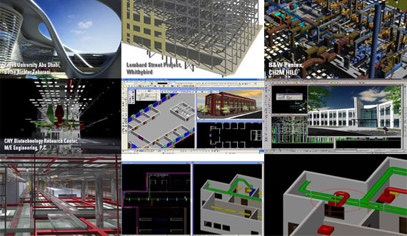
AECOsim is built with the AECOsim Building Designer, a 3D CAD package that is useful for multi-disciplinary design, incorporating design, running simulations and locating design conflicts prior to construction of the building physically. AECOsim Building Designer also comes with realistic rendering capacity which offers renderings of the completed project.

AECOsim also contains the hypermodeling features that can be used to put in markers into the design and the viewer will be able to find out the section, drawing or sheet for that specific part of the design. The can get a quick cross-reference as well as view details devoid of losing the position in the key model.

There exists a AECOsim Energy Simulator that facilitates the mechanical and electrical engineers to reproduce energy requirements, environmental conditions and their requirements for designing these systems to fulfill the requirements of the building.

AECOsim is well suited with all of Bentley’s other software solutions, with in-built solar shading features, the ability to export to gbXML for energy analysis, and incorporation with packages from other vendors.

The latest version of AECOsim is AECOsim Building Designer V8i

AECOsim is an exclusive BIM package to create any building design in realtime

~~~~~~~~~~~~~~~~~~~
Published By
Rajib Dey
~~~~~~~~~~~~~~~~~~~

Wednesday, July 30, 2014

PTC Creo Elements/Direct is an exclusive 3D CAD application for mechanical engineers and 3D designers:

PTC Creo Elements/Direct that is known as CoCreate earlier provides solution on direct modeling design from start to finish. This state-of-the-art 3D CAD software contains an all-encompassing system that is made with part and assembly structure having incorporated product data management useful for the mechanical engineers and designers to fulfill their requirements.

PTC Creo Elements/Direct comes with direct 3D CAD, CAE and product data management that offers the best possible level of design suppleness.

The latest version of PTC Creo Elements/Direct is version 19.0 that consists of latest and advanced features to facilitate the designers for accomplishing day-to-day design tasks quickly as well as making more time for product development teams to invent and make the product quality better.


PTC Creo Elements/Direct is an exclusive 3D CAD application for mechanical engineers and 3D designers
3D Cad


~~~~~~~~~~~~~~~~~~~~
Published By
Rajib Dey
www.bimoutsourcing.com
~~~~~~~~~~~~~~~~~~~~

Monday, July 28, 2014

How to install Revit for Mac devices

This exclusive video tutorial is presented by Revit LT. We are going to show you how to install Revit for Mac devices using a third party program called Parallels. Many people are frustrated that Autodesk have yet to make native Revit for Mac however we have found that running Revit or Revit LT on a Mac using Parallels presents no real performance issues.

First, visit the Parallels website and install a free trial version of Parallels Desktop for Mac (latest version). Once It has installed, double click the desktop Icon to launch Parallels desktop. From within the Parallels Windows Interface, connect to the web and visit www.Autodesk.com/revitlt. Download a free 30 day trial of Revit LT by filling out the information and Thats it! Now you can run Revit LT for Mac using Parallels Desktop.


~~~~~~~~~~~~~~~~~~~
Published By
Rajib Dey
www.bimoutsourcing.com
~~~~~~~~~~~~~~~~~~~

Sunday, July 27, 2014

Create 3d parts of your machine instantly with MeshCAM

GRZ software introduces MeshCAM, a useful CNC software for non-machinist that can produce gcode in the quickest possible time.

The users can apply this software to create any parts which can’t be made through a conventional CAD program. The users have to just open any image file and apply MeshCAM to transfer to a 3D surface to be machined directly.

MeshCAM is compatible with almost all 3D CAD programs & 3d modeling software like Rhino, Solidworks, Autodesk Inventor, Viacad, Blender, Sketchup, Tinkercad, Autocad, Alibre, ZBrush etc. It can perform with the two most common 3D file formats like STL and DXF.

If any user prefers to create 2D parts devoid of applying a 3D CAD program, just load 2D DXF files (in R12 format) and extrude them to a 3D part.

The users can click will be able to characterize particular regions.

You can click through the 3D window as well as load an outline from any cad program by characterizing particular regions to be machined. This aspect will be helpful to re-machine a segment of a part or machine a tiny, detailed section of your part. In that case you don’t have to machine the total object.

With MeshCAM, the users get rid of the problem for identifying the exact area to machine. The users can perform it through a check box by informing to machine the total object only the area the area wrapped by the parts.

MeshCAM contains several toolpath options like below:-

  • Parallel Roughing (planar and 3D).
  • Contour Offset Roughing (Planar and 3D).
  • Parallel Finishing ( X or Y direction).
  • Waterline Finishing.
  • Pencil Finishing

This series of toolpaths can machine almost any part according to your choice.

MeshCAM is incorporated with Cutviewer, a CNC simulator. The users load the gcode at once devoid of reentering any information about cutters or stock size. With this feature, the users will be able to quickly view the appearance of the parts with no wasted time, cutters, or stock.

MeshCAM contains an in-built post processor to convert the gcode to work with your machine. It supports several machine types as-is and it can be expanded to support various other.

Download a free 15-day trial version.


Create 3d parts of your machine instantly with MeshCAM

~~~~~~~~~~~~~~~~~~~
Published By
Rajib Dey
www.bimoutsourcing.com
~~~~~~~~~~~~~~~~~~~

Thursday, July 24, 2014

An exclusive online BIM Event on BIM for manufacturer

Initially the impact of BIM can be found for construction industry but gradually the application of BIM has been extended to several manufacturing and other sectors.

In order to place them ahead of competition, various manufacturers are looking for BIM (Revit Model) data.

Adris MicroCAD is presenting an online webinar that focus on how BIM can provide huge benefits to manufacturing industries.

There is no specific schedule date for the webinar. Register your seat online and the organizer will contact you when a date will be available.


~~~~~~~~~~~~~~~~~~
Published By
Rajib Dey
www.bimoutsourcing.com
~~~~~~~~~~~~~~~~~~

Wednesday, July 23, 2014

Online Cad Program to make 3d modeling floor plan with AutoCAD

Mufasu CAD presents a useful video tutorial for professional CAD users. This exclusive tutorial is based on AutoCAD that focuses on how generate 3d modeling floor plan efficiently.


~~~~~~~~~~~~~~~~~~~~~
Published By
Rajib Dey
www.bimoutsourcing.com
~~~~~~~~~~~~~~~~~~~~~

Monday, July 21, 2014

Some useful tricks to cut/copy & paste text from word to AutoCad and Revit

Joe Eichenseer, a Building Solutions Team Manager with IMAGINiT Technologies, has presented some useful tricks on how to cut/copy & paste text from a doc file to AutoCad and Revit.

Several Students as well as clients always face problems while going to cut & paste text properly from Microsoft Word into AutoCAD & Revit, and vice versa.

If anyone follows the general process like highlight text in Word, and then just paste it into AutoCAD or Revit, he/she may not get desired results.

In AutoCAD, one will receive non-editable raster text having a white background. In Revit, it seems that paste function will not work. The easiest way to have vector text to paste properly is to turn on a text box prior to copy or paste the text.

Maintain the following processes to Copy Text properly from Microsoft Word into AutoCAD or Revit:

  • Highlight the text in Word & COPY to Clipboard (shortcut key CNTRL+C).
  • In either AutoCAD or Revit go with the TEXT command.
  • To initiate the text box, click the mouse in the drawing area.
  • Paste the text into the text box (shortcut key CNTRL+V).

Process for copying Text properly from AutoCAD or Revit into Microsoft Word:

  • In AutoCAD or Revit, to turn on the text box, double click on the text box from where one likes to copy from.
  • Highlight the text within the activated text box, and COPY to Clipboard (shortcut key CNTRL+C).
  • Paste into Microsoft Word (shortcut key CNTRL+V).

Some useful tricks to cut/copy & paste text from word to AutoCad and Revit
~~~~~~~~~~~~~~~~~~~
Published By
Rajib Dey
www.bimoutsourcing.com
~~~~~~~~~~~~~~~~~~~

Friday, July 18, 2014

Tag Improvements with Revit 2015

This exclusive video tutorial is presented by Autodesk Building Solutions. Now when you move a tagged element, or drag the tag head, the tag leader and elbow adjustment behavior is now consistent with that of text leaders.

Additionally the instance property Elevation at Top has been added to isolated foundations, wall foundations, and foundation slabs.


~~~~~~~~~~~~~~~~~~~
Published By
Rajib Dey
www.bimoutsourcing.com
~~~~~~~~~~~~~~~~~~~

Tuesday, July 15, 2014

Topcon introduces cloud based ScanMaster v3.0 compatible with BIM

Topcon Positioning Group launched the most updated version of its laser scanner software package alias ScanMaster v3.0.

ScanMaster consists of tools for accumulating, processing, editing and distributing 3D point cloud data from a laser scanner for diversified applications. By integrating the Topcon GLS family of laser scanners, with ScanMaster software, one can get complete BIM (building information modeling) environment functionality.

ScanMaster system comes with a cloud-to-cloud registration solution that facilitating improving field and scanning workflows.

ScanMaster v3.0 allows practitioners, who apply third-party scanners, to enjoy the superior quality workflow as compared to Topcon GLS customers.

The improved cloud-to-cloud registration ability can considerably reduce the requirement to set targets — even in the most complicated work situations. This feature can also expands the well-organized application of 3D laser scanners that range from mining deformation projects and accident reconstruction applications — where the placing of targets are considered as a factor of safety.

ScanMaster facilitates the professionals in a wide array of fields to accumulate point cloud data efficiently, then develop and generate final deliverables.

ScanMaster v3.0 alos contains some added features like FARO file import options, ASTM E57 file import and export operations, point cloud library (PCD) file import and export functionality, cleanup and region selection tools, volume calculation and automatic edge set extraction.

Topcon introduces cloud based ScanMaster v3.0 compatible with BIM

~~~~~~~~~~~~~~~~~~~
Published By
Rajib Dey
www.bimoutsourcing.com
~~~~~~~~~~~~~~~~~~~

Automated LEED Daylighting for Revit users

This exclusive video tutorial is presented by Autodesk Building Solutions. Award-winning Architecture firm D/P/S was an early adopter of the new automated Daylighting for LEED feature. Learn how Lighting Analysis for Revit helps them improve designs and increase value for their clients.www.autodesk.com/products/lighting-analysis-revit.


~~~~~~~~~~~~~~~~~~~
Published By
Rajib Dey
www.bimoutsourcing.com
~~~~~~~~~~~~~~~~~~~

Sunday, July 13, 2014

Autodesk Revit 2015 - Greater Accuracy of As-Built Model Definition

This exclusive video tutorial is presented by Autodesk Building Solutions. In Autodesk Revit 2015 there are some new capabilities and features to enable a precise definition and placement of structural framing elements in space.


~~~~~~~~~~~~~~~~~~~
Published By
Rajib Dey
www.bimoutsourcing.com
~~~~~~~~~~~~~~~~~~~


Thursday, July 10, 2014

ASI, LLC Offers 3D Models for BIM

With over a decade of experience, Atlantic Subsurface Imaging, LLC started out by offering utility mapping in Philadelphia. Now, Atlantic Subsurface Imaging, LLC has expanded into many similar areas of service. Plus, Atlantic Subsurface Imaging, LLC has expanded into a larger geographical area. However, the customer has always been the number one area of focus at Atlantic Subsurface Imaging, LLC. With improved technology, Atlantic Subsurface Imaging, LLC can now offer their customers 3D models to help assist in project planning.

Atlantic Subsurface Imaging, LLC has learned a lot over the past ten years. More information about a subsurface area is always an asset to a customer during project planning. Atlantic Subsurface Imaging, LLC utilizes the revolutionary LiDAR technology. LiDAR is essentially a laser scanning technology that allows for some of the most precise measurement of an area. LiDAR technology can assist Atlantic Subsurface Imaging, LLC in creating 3D models for their customers.

ASI, LLC Offers 3D Models for BIM

LiDAR technology is a great resource. However, Atlantic Subsurface Imaging also utilizes industry-leading ground penetrating radar technology in conjunction with the laser scanning ability. These two resources together are what allow Atlantic Subsurface Imaging, LLC to create extremely detailed 3D models. Furthermore, Atlantic Subsurface Imaging, LLC uses the most advanced 3D software scanning software available.

All of the 3D designs produced are compatible with CAD, BIM, and GIS. Atlantic Subsurface Imaging, LLC is able to provide some of the most accurate descriptions of subsurface areas in the industry. Atlantic Subsurface Imaging, LLC has helped to build 3D models for everything from small projects to major highways. Whether a small business owner is looking for utility mapping in New York or 3D models for pre-construction, Atlantic Subsurface Imaging, LLC offers fast and reliable service.

ASI, LLC Offers 3D Models for BIM

~~~~~~~~~~~~~~~~~~~
Published By
Rajib Dey
www.bimoutsourcing.com
~~~~~~~~~~~~~~~~~~~

Tuesday, July 8, 2014

What's New in Autodesk Revit Structure 2015

In this live customer event recording, CAD Technology Center presents an overview of the new structural design features of Autodesk Revit 2015.


~~~~~~~~~~~~~~~~~~~
Published By
Rajib Dey
www.bimoutsourcing.com
~~~~~~~~~~~~~~~~~~
 

Monday, July 7, 2014

Use 2D sheets and 3D models to Navisworks project with Navisworks 2015 PDF Reader

Autodesk Navisworks 2015 PDF reader facilitates the users to insert 2D PDF sheets to their Navisworks project. Apply 2D sheets and 3D models in a solitary project surrounding to take off quantities and evaluate your project.

Autodesk Navisworks 2015 PDF provides the following benefits to the users:-

  • Organize your quantity takeoff through any of the 50+ file formats and now PDF as data source.
  • Incorporate the PDF sheets in the project browser to be able to look through page thumbnails, rapidly jump to pages and set up the sheets as per your need or arrange all at once.
  • Toggle among the 3D model and 2D sheets effortlessly.

General Usage Instructions: The users will be able to include PDF sheets to the project throug the “Append” command or the “Import Sheets & Models” command available in the Project Browser. The users have to set the scale by hand as PDF files do not have scale information. This can be easily performed by visiting menu View > Windows > Put in Scale by Measurement. Here the users can opt for one or more distances and put in the distance to determine the scale.

The users can manage visual fidelity with the ‘Resolution(DPI)’ setting accessible in the Options Editor for the PDF File Reader. Press F12 and direct to File Readers > PDF. The default value is 300 and will be compatible with most cases.

For having more detail, the users can raise this value, but be conscious of that this also augments memory requirements and may affect performance. The users may also reduce the value to lessen memory requirements. The users must refresh the sheet to re-import with the modified settings.

Use 2D sheets and 3D models to Navisworks project with Navisworks
~~~~~~~~~~~~~~~~~~
Published By
Rajib Dey
www.bimoutsourcing.com
~~~~~~~~~~~~~~~~~~

Types of Clash detection and their importances

Clash detection is a popular term among AEC firms. It is 3D graphic that permits for the inherent exposure of inconsistencies in early phase of the design. Detecting inconsistencies is very important, as these can provide serious effect on the construction progression, result in delays, design modifications, materials costs and budget overruns.

The constructability issues are solved in earlier stage of construction and it saves huge amount of money, time which lead to creating a superior building.

Clash detection is a part and parcel of the BIM modeling system. In BIM modeling process, there is not a single model but various models are incorporated into a combined master model. Each discipline ranging from structural engineering, MEP engineering, environmental engineering, etc makes a model independently on the basis of the architect’s original model. It is the starting point for all the other disciplines. Once each of the disciplines completes their work, the next stage in BIM modeling is clash detection.

Therefore, clear conception on clash and how to apply clash detection factors in BIM software is vital for engineers, architects, owners and contractors. It is found that each recognized clash saves $17,000 approximately on a project.

Clash detection is also considered to be an effective teaching tool that facilitates the students to find out prospective mistakes devoid of spending wasteful time searching through 2D drawings.

Generally there are three types of clashes:

  • Hard clash
  • Soft Clash/Clearance Clash
  • 4D/Workflow Clash

Hard Clash: A hard clash occurs when two objects take up the identical space. For example, a beam is going through where a plumbing run is designed. As information is implanted in the BIM modeling objects, hard clash provides geometry based detection as well as semantic and rule-based detection algorithms. Geometry based clash detection will restore a clash for every recessed ceiling light, or a pipe going through a wall. But if clash detection rules are created on the basis of embedded object data, it can reduce these types of general errors. The level of detail and selection sets plays an important role in BIM modeling for the accurateness and effectiveness of clash detection by performing clash detection amid definite subsets of a model.

Soft Clash: Soft clashes denote objects that require positive spatial/geometric tolerances, spaces and buffers inside their buffer zone for access, insulation, maintenance or safety. Soft clashes create new possibilities where BIM modeling clash detection brings new potential to the method. Custom “soft clash” detection can be applied for testing components for building code adherence.

4D/Workflow clash: 4D/Workflow clash detection can determine scheduling clashes for work crews, equipment/materials fabrication & delivery clashes and other project timeline issues through a BIM modeling project.

~~~~~~~~~~~~~~~~~~~~
Published By
Rajib Dey
www.bimoutsourcing.com
~~~~~~~~~~~~~~~~~~~~


Friday, July 4, 2014

BIM is an effective tool for 4D construction conflict management analysis

Now-a-days the various new aspects of BIM are emerging out. How BIM and 4D scheduling can bring huge benefits to construction safety, is the most controversial topic of today. There exists several incorporated technological and management practices which are associated with the site safety. At the initial stage, BIM comes with supreme accurateness and self-reliance in project documents which consecutively speed up the prefabrication process, minimize the time spent on site as well as reduce the possibility of on-site accidents.

4D scheduling facilitates the designer and project stakeholders to detect collisions at the initial design phase and examine congestion and accessibility more efficiently as compared to standard Gantt charts.

The most striking features of 4D schedules are that, they are different from a static building model and remain in a dynamic state; identical to the building itself. By relating time to structural components, a structural engineer gets the ability to perform structural analysis associated with time through the actual BIM model. If this is undertaken at initial design stage, it may find out the desirable material and the construction methodology with the purpose of saving time and money.

There are 3 fundamental elements of safety in 4D scheduling:

  • 4D structural safety analysis.
  • 4D construction conflict management analysis.
  • 4D layout collision analysis and management.

It is assumed that these types of extensive rules for 4D scheduling could significantly enhance the safety inside the construction industry.

BIM contains algorithms to produce rule based checking systems for safety which is the prospect of this technology. The algorithms entailed on the basis of existing legislation and best practice. As for instance, 4D scheduling of definite site risks, may imply warning signage or tape or in the case of more serious risks, handrails.

BIM is an effective tool for 4D construction conflict management analysis  
~~~~~~~~~~~~~~~~~~
Published By
Rajib Dey
www.bimoutsourcing.com
~~~~~~~~~~~~~~~~~~


Thursday, July 3, 2014

Revit Energy Analysis with Thermal Properties for Windows

This video explains how to enable and change the thermal properties of building elements in your Revit model. This video specifically changes the window thermal properties.

This video is part of the Whole Building Energy Analysis with Revit professional course. 

~~~~~~~~~~~~~~~~~~~
Published By
Rajib Dey
www.bimoutsourcing.com
~~~~~~~~~~~~~~~~~~~

FormIt and RevIt

We illustrate how to use FormIt to model your ideas in 3d then smoothly move them into Revit. Then, wee show the abundant functionality available in Revit to produce a conceptual design presentation based on your FormIt model.


~~~~~~~~~~~~~~~~~~
Published By
Arka Roy
www.bimoutsourcing.com
~~~~~~~~~~~~~~~~~~

Tuesday, July 1, 2014

ASCON Group launched KOMPAS-3D v15 for advanced parametric 3d modeling

ASCON Group, the leading solution provider in high-performance CAD/AEC/PLM software systems, just launched the most updated version of KOMPAS-3D Home alias KOMPAS-3D v15. The part-time designers, hobby designers, hobby engineers as well as full-time students can use this parametric software for non-commercial purpose.

KOMPAS-3D Home is an easy to use 3D modeling application that facilitates the users to 3D models parametrically. Parametric technology is supported with a single prototype and can create a wide array of products instantly.

KOMPAS-3D Home contains some useful functions which can generate precise plans, concise diagrams, documented reports as well as vector-based illustrations output in PDF format. There is drawing editor incorporated with it which offers diversified design disciplines through adjustable and automatic work processes.

The innovative KOMPAS-ABC learning system comprising several instances of 3D models, 2D drawings, and surface models, allows the users to be familiar with CAD through self-study and apply the functions of KOMPAS-3D Home efficiently.

KOMPAS-3D Home comes with professional surfacing commands which empower users to make simple or complicated shapes as per the design requirements.

The users can also model virtual body surfaces containing a thickness of zero, the type of flexible body useful for composite geometries.

KOMPAS-3D Home is based on a specifically developed version of Ascon group’s own modeling kernel that integrates the features of parametric construction, history-based design, and direct modeling essential for solids as well as surfaces modeling.

KOMPAS-3D Home is compatible with DWG, DXF, and STEP having ability to read design files from a series of other CAD, CAM, and CAE systems as well export to them.

The users can export drawings and models in raster formats like TIFF for technical documentation and JPEG for Web site designs.

The users can access this parametric software for 70 Euros (US$95).

Download the free demo version.

ASCON Group launched KOMPAS-3D v15 for advanced parametric 3d modeling  

~~~~~~~~~~~~~~~~~~~~~
Published By
Arka Roy
www.bimoutsourcing.com
~~~~~~~~~~~~~~~~~~~~~