adsense analytic

Showing posts with label building model. Show all posts

Saturday, April 13, 2019

AMC Bridge upgrades Revit to Kineo

Revit® to Kineo™ is a technology presentation for Autodesk® Revit® supported with the Siemens Kineo™ software to work out the paths necessary for shifting an object within a building model. It facilitates you to visualize the transition of the object along the estimated path in a 3D animation.

Revit to Kineo offers the following functionalities :-


• Choose an object to move.

• Choose obstacles to circumvent.
• Establish the parameters of the model and the obstacles.
• Arrange the start and end points of the path.
• Measure the path.
• Adjust or smoothen the resulting path to obtain the optimum length.
• Export the path to Revit for animation.
• Play or reset the animation, step it backward or forward in Revit.

Compatibility:


• Windows operating system.

• Autodesk Revit.
• A separate Kineo license.

For online demonstration of Revit to Kineo, watch the following video tutorial.
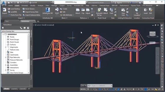

AMC Bridge upgrades Revit to Kineo

Read more
~~~~~~~~~~~~~~~~~~~~~~~~
Published By
Rajib Dey
www.bimoutsourcing.com
~~~~~~~~~~~~~~~~~~~~~~~~
Tuesday, December 18, 2018

An exclusive tutorial on rooms in Revit

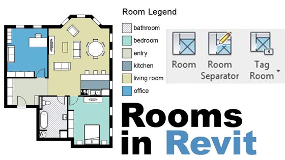
In this exclusive revit tutorial, you will get details about rooms in Revit like location of rooms in your projects, how the rooms can be presented in a superior way with colors, how the information can be pulled out from your model to obtain information (area, perimeter, finishes etc.) concerning your rooms.


Get some useful notes on rooms in Revit :-
Open a plan view and apply the Room tool to arrange rooms in the building model.
Automatically set rooms in all closed and bounded areas on the current level.
By default, rooms are never demonstrated in plan views and section views. However, it is possible to modify the visibility/graphic settings to generate rooms and their reference lines observable in these views.

It is possible to copy rooms from one phase to the next to retain their properties.
In order to allocate information regarding the rooms and spaces in a model, an architect and a mechanical engineer have to utilize linked models or worksharing.
Revit employs room boundaries while measuring the area, perimeter, and volume of a room.
Revit can work out the area and volume of rooms and demonstrate the information in schedules and tags.

To get more details, go through the following Revit video tutorial.

Video Source: Balkan Architect

An exclusive tutorial on rooms in Revit

~~~~~~~~~~~~~~~~~~~~~~~~
Published By
Rajib Dey
www.bimoutsourcing.com
~~~~~~~~~~~~~~~~~~~~~~~~

Friday, November 30, 2018

Some useful tips to draw front elevation in AutoCAD

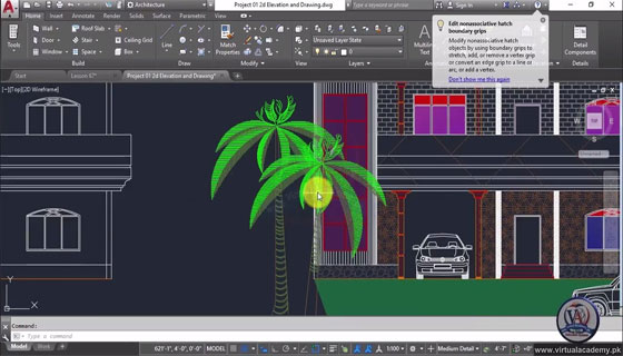
In this autocad video tutorial, you will learn some useful tips to draw front elevation of any building.

Once a elevation line is drawn, it is necessary to extract an elevation from the elevation line and the objects picked up in the building model.

As soon as a 2D elevation is created, the object produced is a 2D Section/Elevation object. Both 2D sections and elevations contain the equivalent object type and style.

Prior to generate an elevation, thaw and activate all layers of objects in the building model that should be contained in the elevation. The Objects on layers which are off or frozen cannot be segment of the selection set for the elevation. To make the performance better, deactivate the layers of the objects that should not be contained in the elevation.

2D Elevations: 2D elevations are produced by drawing an elevation line in front of a number of objects and then generating a 2D elevation object out of them. The elevation object is drawn devoid of hidden and overlapping lines.

It is possible to edit a 2D elevation by modifying its object display properties or its style display properties. The 2D elevation style facilitates the users to include display components to the display illustration of the elevation and develop rules that assign various parts of the elevation to several display elements.

The visibility, layer, color, linetype, lineweight, and linetype scale of every elements can be easily managed. It is also possible to assign a material like a brick or concrete hatch, to individual components of the object or the style. Furthermore, you can use linework editing commands to assign lines in a 2D elevation to several display elements, and combine geometry into a 2D elevation. The users can dimension 2D elevations.

3D Elevations: 3D elevations are produced by drawing an elevation line in front of a number of objects and then generating a 3D isometric elevation object out of them. The styles are not employed in 3D elevations.

The display of subdivisions inside 3D elevations can be managed easily. With the use of the Hidden Line Projection command, the users can generate 2D hidden line projections of any view of the 3D elevation that can be exploded and edited or hatched.

To learn the tricks to draw front elevations in AutoCAD easily, go through the following video tutorial.

Some useful tips to draw front elevation in AutoCAD

Read more
~~~~~~~~~~~~~~~~~~~~~~~~
Published By
Rajib Dey
www.bimoutsourcing.com
~~~~~~~~~~~~~~~~~~~~~~~~
Friday, February 9, 2018

How To Produce Solar/Shadow Studies With Revit

Prior to start a solar study, organize a view to show light and shadows. Apply the following useful tips :-
• Generate a 3D view.


To show light and shadows efficiently on a project, apply 3D views of the building model. Show standard plan views like floor plans and ceiling plans, abstain from demonstrating various elements in 3D, therefore, there will be no shadows to be casted from these elements.

The sun path and shadows can be accessed in all 3D views devoid of those applying the Wireframe or Consistent Colors visual style. In 2D views, the sun path can be accessed in floor plans, reflected ceiling plans, elevations, and sections.

Note: The sun path’s on-screen controls can’t be edited in perspective, walkthrough, or rendered 3D views.

• Rotate a view to True North to perfectly demonstrate the position of the sun concerning the project through solar study.
• While creating a lighting solar study, state the location of the sun corresponding to the view.


Source: knowledge.autodesk.com

How to produce solar/shadow studies with Revit

~~~~~~~~~~~~~~~~~~~~~~~~
Published By
Rajib Dey
www.bimoutsourcing.com
~~~~~~~~~~~~~~~~~~~~~~~~

Monday, January 30, 2017

How To Apply A Solar Design Study In Revit

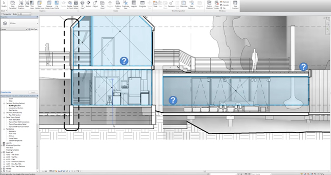
This Revit video tutorial provides detailed information on how to create a solar design study in Revit. The tutorial will be useful for building construction. Solar studies in Revit demonstrate the effect of natural light and shadows on the building model.

It is a very quick and simpler method. Initially, you have to establish what view you prefer to run the solar study. It can range from your Site plan, elevations, default 3D view or an internal camera view. The procedure is identical for all. Once you get your desired view, you should configure the sun settings. Choose the Sun path button on the view control bar along the bottom of the drawing window and opt for “Sun settings” to expose the sun settings dialogue box.

With Solar studies, one will be to visualize the effect of natural light and shadows on the exteriors and interiors of projects.

Apply solar studies to realize how shadows from terrain and adjacent buildings impact a site, or where natural light infiltrates a building at particular times of the day and year.


By providing the effect of natural light and shadows on your project, solar studies produce useful information that can help creating impressive passive solar design.

~~~~~~~~~~~~~~~~~~~~~~
Published By
Rajib Dey
~~~~~~~~~~~~~~~~~~~~~~