adsense analytic

Showing posts with label Structural Steel. Show all posts

Tuesday, December 24, 2019

BIM Case Study: Circuit of the Americas Observation Tower

In the modern construction industry, the usage of BIM software has become invaluable. Without Building Information Modeling the industry today will be nowhere to meet the demands and challenges of the 21st-century construction projects. By reviewing real-life scenarios of BIM usage, we can identify and analyze how exactly experts are using the applications to support building development and project management.

The very first racing track solely built for Formula One racing in the USA, the Circuit of the Americas is 3.5 miles long and respectively wide. This grade 1 FIA-specification prestigious motor racing track hosts both car races and motorbike races and has already hosted some of the prestigious motor races in the world. For today's BIM case study, let us see how BIM software was used in the construction of the observation tower for these tracks.
Project Requirement

The Circuit of the Americas (CotA) race track is 3.426 miles (or 5.514 kilometers) long, with a width proportional to the circuit. The race track sits upon 890 acres of undeveloped land in southeastern Travis County near Austin, Texas. The duty of designing the observation tower for this track was endowed to Mio Rivera, who invented a brilliant design reminding the visitors why they are here.

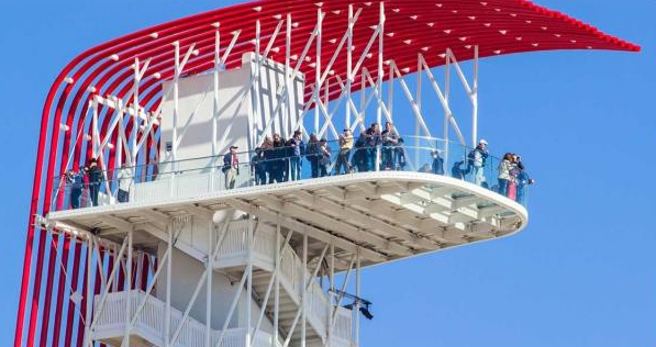
The observation tower for the track is 251 feet or 77 meters tall and is capable of seating an audience ten thousand strong. A double-helix structure surrounds the elevator hoist-way that is the main connection to the grounds to the building. The 900 sqft main observation deck has a partial glass floor and offers a 360-degree view of the surroundings as well as downtown Austin from an elevation of 230 feet.

But the most obvious feature of the building is its 18 steel tubes, colored a vivid, bright red, running along the back of the tower and gracefully flowing down to horizontal. This unique design is intended to act as a dramatic focal point for the race track and serves the visitors' as an anchoring point for racing, reminding them of the bright tail light streak left behind after a speeding car. The 8” diameter tubes not only have a strong visual impact but also contribute to the structural stability of the tower by acting as an outrigger column for lateral load resistance via a series of struts and rods that tie back to the primary structure.

BIM Case Study: Circuit of the Americas Observation Tower

~~~~~~~~~~~~~~~~~~~~~~~~
Published By
Rajib Dey
www.bimoutsourcing.com
~~~~~~~~~~~~~~~~~~~~~~~~

Tuesday, August 29, 2017

Download cad drawings of Reinforced Concrete Retrofit at discounted prices

Download extensive lists of reinforced concrete retrofitting / repair / strengthening drawing details which are available in cad dwg, dxf and pdf formats. All the drawings are in 1:10 scale.

Seismic retrofitting refers to the alteration of prevailing structures to improve their resistance capacity against seismic activity, ground motion, or soil failure caused by earthquakes.

The cad drawings include the following :-
• Concrete Column Steel Jacketing
• Concrete Column Jacketing Detail
• Column Jacket Anchorage to slab beam
• Column Jacketing Foundation Footing Detail
• Continuous Floor to Floor Column Jacketing
• Discontinued Floor to Floor Column Jacketing
• Partial Concrete Column Jacketing
• Concrete Beam Jacketing Details
• Steel Jacketing Reinforcement of Concrete Beam
• Carbon Fiber strengthening of Concrete Beam

You can apply these drawings in your project and save significant times.

To download the drawing, click on the following link www.structuraldetails.civilworx.com


Read more

~~~~~~~~~~~~~~~~~~~~~~~~
Published By
Rajib Dey
www.bimoutsourcing.com

~~~~~~~~~~~~~~~~~~~~~~~~

Thursday, August 24, 2017

Demonstration of new freeform rebar tool in Revit 2018.1

This exclusive revit video tutorial provides the demonstration of new freeform rebar tool that is accessible in Revit 2018.1

This latest tool facilitates the users to include straight bars (Shape Code 00) which are based on complicated surfaces. The bars will produced a complicated shape but stay straight for fabrication instructions.

The Freeform Reinforcement tool is applied in a 3D view by initially choosing the host face. This tool applies the Select Multiple option. With the help of space bar, validate the selection. Then, choose the starting surface and then the ending surface and lastly press enter to set the bar.

This tool is mostly suitable while going to model complicated Architecture and Civil structures like bridges and tunnels. Each bar should have been scheduled for a precise length.

Free Form Rebar can contain any geometry in the form of planar or 3D, and can be utilized for modeling and detailing of reinforcement in complicated 3D structural elements.

Rebars are generated at the cover distance out of the intersection of the references which the Revit user chooses. One reference is made with one or more structural element faces.

The Surface Distribution rebar type comprises of bars that change among the Start Surface and the End Surface and are circulated along the Host Surface.

Free Form Rebar belongs to the Structural Rebar category, and contain all the properties related to it. Free form Rebar can be formed as single bars or rebar sets, rebar quantity for each instance of a Free Form Rebar can be modified easily.

Then the rebar constraints can be controlled with in canvas tools in 3D views to organize improved and perfect rebar placement.


It is possible to utilize adjustable numbering settings and generate perfect shop drawings with schedules that demonstrate varying lengths in Free Form Rebar sets to make the fabrication better.


Read Continue


~~~~~~~~~~~~~~~~~~~~~~~~
Published By
Rajib Dey
www.bimoutsourcing.com
~~~~~~~~~~~~~~~~~~~~~~~~