adsense analytic

Tuesday, December 24, 2019

BIM Case Study: Circuit of the Americas Observation Tower

In the modern construction industry, the usage of BIM software has become invaluable. Without Building Information Modeling the industry today will be nowhere to meet the demands and challenges of the 21st-century construction projects. By reviewing real-life scenarios of BIM usage, we can identify and analyze how exactly experts are using the applications to support building development and project management.

The very first racing track solely built for Formula One racing in the USA, the Circuit of the Americas is 3.5 miles long and respectively wide. This grade 1 FIA-specification prestigious motor racing track hosts both car races and motorbike races and has already hosted some of the prestigious motor races in the world. For today's BIM case study, let us see how BIM software was used in the construction of the observation tower for these tracks.

Project Requirement

The Circuit of the Americas (CotA) race track is 3.426 miles (or 5.514 kilometers) long, with a width proportional to the circuit. The race track sits upon 890 acres of undeveloped land in southeastern Travis County near Austin, Texas. The duty of designing the observation tower for this track was endowed to Mio Rivera, who invented a brilliant design reminding the visitors why they are here.

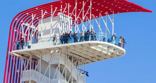
The observation tower for the track is 251 feet or 77 meters tall and is capable of seating an audience ten thousand strong. A double-helix structure surrounds the elevator hoist-way that is the main connection to the grounds to the building. The 900 sqft main observation deck has a partial glass floor and offers a 360-degree view of the surroundings as well as downtown Austin from an elevation of 230 feet.

But the most obvious feature of the building is its 18 steel tubes, colored a vivid, bright red, running along the back of the tower and gracefully flowing down to horizontal. This unique design is intended to act as a dramatic focal point for the race track and serves the visitors' as an anchoring point for racing, reminding them of the bright tail light streak left behind after a speeding car. The 8” diameter tubes not only have a strong visual impact but also contribute to the structural stability of the tower by acting as an outrigger column for lateral load resistance via a series of struts and rods that tie back to the primary structure.

BIM Case Study: Circuit of the Americas Observation Tower

~~~~~~~~~~~~~~~~~~~~~~~~
Published By
Rajib Dey
www.bimoutsourcing.com
~~~~~~~~~~~~~~~~~~~~~~~~

Friday, December 20, 2019

BIM Case Study: Oakland International Airport’s Central Utility Plant

Growing in both capability and application, BIM (Building Information Modeling) methodology is fast becoming famous with numerous followers. BIM software is becoming integral in large constructions to efficiently and properly create appropriate information in a suitable format at the right time so that better decisions can be made throughout the design, construction, and operation of built assets.

To understand how professionals around the world are using the assistance of this software in real life to build various types of residential, commercial, industrial, and infrastructure projects, we will need to study some examples of live BIM uses.

Today, we will study the case of constructing the Central Utility Plant for the Oakland International Airport in Oakland, California, so that we can understand how BIM software was used in this project.

Project Requirements:
In early 2012, the Turner Construction Company based in New York was engaged to start the construction of a Utility Plant for the Airport in Oakland, CA. About 8300 square feet in size, this facility was to house an extremely intricate network of electrical, heating, ventilation, and air conditioning systems. All of these systems are critical to keeping the airport running efficiently around the clock. The project was divided into two parts - to construct the new mechanical building T1MB, and to renovate the building M104. Scope of operations for this project are:

1. Renovation of Building M104, and the existing Terminal 1 Central Utility Plant
a. Architectural enhancements
b. Interior space modifications
c. New roofing and drainage
d. Replacement of heating and ventilation systems
e. Replacement of lighting and lighting control systems
f. Seismic upgrade of the building
g. Upgrade of the fire alarm system and installation of a new fire protection system

BIM Case Study: Oakland International Airport’s Central Utility Plant

~~~~~~~~~~~~~~~~~~~~~~~~
Published By
Rajib Dey
www.bimoutsourcing.com
~~~~~~~~~~~~~~~~~~~~~~~~

Wednesday, December 18, 2019

Use of GIS in BIM

The construction industry has come far on the shoulders of digital computing. Software usage is standard now in designing, modeling, cost estimation, and project management with every constructor now. Particularly, BIM (Building Information Modeling) software has become common in every project from small residential to giant infrastructure construction.

However, a major headache of the AEC’s (Architects, Engineers & Constructors) is data loss between the planning and development phases. Whenever you transmit data from one software to another, the receiving application translates the data in its own custom ways. What it cannot translate, it rejects as garbage. After that, the AEC has to recreate the lost data in the plan again. The more software stages your project has, the more this problem will occur, the more complicated this situation will become and the more the error margin will grow.

However, the rapid evolution in the cloud-based data storage, vending, and analysis technologies can be taken advantage of to patch these leaks. Specifically, the GIS (Geographic Information System) can be very handy when merged with or used in parallel to BIM applications. Let us delve deeper into the subject in this article.

What is GIS
A geographic information system (GIS) is a computer system for capturing, storing, checking, and displaying data related to positions on Earth's surface. GIS is a system designed to capture, store, manipulate, analyze, manage, and present all types of geographical data. The key in this technology is Geography – this means that some portion of the data is spatial. By relating seemingly unrelated data, GIS can help individuals and organizations better understand spatial patterns and relationships.

How can GIS help in BIM
The fusion of BIM and GIS provides the power to build a robust context model where geographic information and infrastructure design data are brought together. Software companies like AutoDesk develop both GIS and BIM software and are now integrating one into the other in order to provide more data clarity and reusability. Adoption of GIS into BIM will give you a fat handful of benefits; the major one being digital data as part of deliverables for each transition. The geographical (and geological) data merged with project plans and drawings will give valuable insights into the AEC’s decision-making process.

Read more
Use of GIS in BIM

~~~~~~~~~~~~~~~~~~~~~~~~
Published By
Rajib Dey
www.bimoutsourcing.com
~~~~~~~~~~~~~~~~~~~~~~~~


Tuesday, October 15, 2019

Download Various 2D Drawing House Plans At Free Of Cost

Explore through an extensive lists of AutoCAD plans along with 3d models and 2D CAD drawings. All these can be downloaded at free of cost.
The list includes house plans, structural plans, concrete blocks, garage plans etc. All the plans are available in .dwg formats.
These house plans are very useful for civil and structural engineers to produce initial designs for sturctures and find out errors prior to production. It will save huge time and resources for them.
One can access these plans from the following link onlinecivilforum.com
Download various 2D drawing house plans at free of cost
~~~~~~~~~~~~~~~~~~~~~~~~
Published By
Rajib Dey
www.bimoutsourcing.com
~~~~~~~~~~~~~~~~~~~~~~~~

Monday, October 14, 2019

Some Useful Tips On Autocad User Interface

The following autocad article provides some useful autocad tips to maintain the standard workspace.
Tricks for AutoCAD user interface - Learn how to deactivate the ribbon and produce a minimum workspace:
1. Give command RIBBONCLOSE
2. Give command MENUBAR 1
3. Select the Tools menu > Toolbars > AutoCAD > Layers
4. Select the Tools menu > Toolbars > AutoCAD > Properties
5. Lots other can be included as per requirements
6. Dock the toolbars at the top of the drawing area
7. Give command MENUBAR 0
8. Click the Workspace button and Save Current As ..., label it “Minimal” or whatever

Some useful tips on Autocad user interface
~~~~~~~~~~~~~~~~~~~~~~~~
Published By
Rajib Dey
www.bimoutsourcing.com
~~~~~~~~~~~~~~~~~~~~~~~~

Saturday, October 12, 2019

Download 1000+ AutoCAD Plans

Given below an extensive lists of autocad plans. The lists consist of near about 1000 modern house autocad plans which can be downloaded easily.
 
These plans contain floor plan, sections, elevations , electric detail and working plan of house. These plans will be useful for the architects and interior designers.
 
These plans are available in .dwg formats. These plans will facilitate the architects to instantly and efficiently draw walls as well as doors and windows.

Read more

Download 1000+ AutoCAD plans

~~~~~~~~~~~~~~~~~~~~~~~~
Published By
Rajib Dey
www.bimoutsourcing.com
~~~~~~~~~~~~~~~~~~~~~~~~

Monday, September 30, 2019

Directly model from laser scans to Revit with InfiPoints Revit Plug-in

Elysium has introduced an advanced functionality to model piping and structures from 3D laser scanned point clouds into Autodesk Revit.
With this feature, the Revit users will be able to minimize their modeling time significantly.
Recently 3D laser scanners are extensively used to capture the on-site environment more completely and precisely. But subsequent modeling of the environment devoid of the proper point cloud software requires huge labor and time.
InfiPoints can automatically draw out the pipes and planes from point cloud data captured from 3D laser scanners. The users then get the ability to generate CAD models with simple clicks of mouse.

Directly model from laser scans to Revit with InfiPoints Revit Plug-in
~~~~~~~~~~~~~~~~~~~~~~~~
Published By
Rajib Dey
www.bimoutsourcing.com
~~~~~~~~~~~~~~~~~~~~~~~~

Thursday, August 29, 2019

Details of Autodesk Revit 2020.1 Update

Autodesk recently introduced the Revit 2020.1 Update that can be accessed via the Autodesk Desktop App or via download from the Autodesk subscription site.
Revit Updates can’t be uninstalled to get back to Autodesk Revit 2020 to its pre-update state. If it is required to eliminate the update, uninstall Autodesk Revit 2020 and then reinstall it.

Given below, some exclusive features of Revit 2020.1 Update.
MEP Systems Analysis: The most exciting features is the inclusion of totally new MEP systems analysis functionality combining with OpenStudio to facilitate custom workflows. The customization varies from local code compliance to integrating certain manufacturer equipment, incorporating analytical to physical modeling together.
At a high level, within Revit, this new feature is suitable for establishing an entire system devoid of modeling any MEP elements.

Banding in Schedules: In schedule views, click on the new Stripe Rows toggle on the Ribbon to illustrate shading in every other row. It does not become visible to show up on sheets or print.
Attach Walls Dialog: The "attach walls" dialog is rectified to make the current selection as the default. To modify, or nullify this, it is required to edit the Revit.ini file.
Path of Travel Tool Updates: The new-to-Revit-2020 Path of Travel tool is totally upgraded. The start and end points are dragged, resulting to an automatic update. The To Room and From Room parameters are shown in schedules and tags. Finally, now there will be a Reveal Obstacles toggle on the Analyze tab.
Site Points observable in Links: The Project Base Point and/or Survey Point from the linked models are now visible inside the host. When the point is shown, and the link is chosen, the point "lights up" and also lists are location data!
Details of Autodesk Revit 2020.1 Update
~~~~~~~~~~~~~~~~~~~~~~~~
Published By
Rajib Dey
www.bimoutsourcing.com
~~~~~~~~~~~~~~~~~~~~~~~~

Saturday, August 24, 2019

Prota Structure 2019 for designing 15 Storied Building

In this video tutorial, you will get step-by-step guidelines for designing a 15-storied building with the use of Pro Structure 2019 software. You will gather knowledge on replicate/generate story, cantilever slab with loading, story with wall load editing etc.
The software is very useful for multi-component modeling and provides complete support for handling steel and concrete structures along with the support for finite element analysis.
The application offers proper solution for handling the construction structures and composite sections together with detailing features and a lot more. The application offers non-linear element transitions and seismic assessment and retrofitting features. Besides, it is very effective for producing the structural designs, customizations and component design management for the design professionals and the engineers.
By utilizing its rapid modeling capabilities, the users will be able to save a significant time and provides support for analytical methods or FE for grouping. This powerful application offers a complete solution toward component design management for the engineers. It can deal with the steel, concrete and composite sections designing with 3D finite element analysis features.

The software offers the following exclusive features :-
• Robust application for multi-component modeling
• Compatible with concrete and steel structures
• Manage composite sections and supports finite element analysis
• An advanced set of tools for scene construction and non-linear analysis
• Seismic review and retrofitting features
• Manage the insulation and dedicated system for structural design
• Customize the designs as per requirements
• Consistent solution for Engineers and design professional
• Design management features and various non-linear element analysis
• Create structural designs and customize the designs accordingly
• Frame structure systems and handle floors and system bases
• Apply analytical methods for FE grouping
• 3D finite element analysis with visual results and precision
• A cost-effective solution with different customizations
• Various other powerful options and features
For online demonstration, go through the following video tutorial.
Prota Structure 2019 for designing 15 Storied Building
~~~~~~~~~~~~~~~~~~~~~~~~
Published By
Rajib Dey
www.bimoutsourcing.com
~~~~~~~~~~~~~~~~~~~~~~~~

Wednesday, August 21, 2019

A position is vacant for experienced Project Architect in NYC

WXY, an award-winning multi-disciplinary practice having expertize in the realization of urban design, planning and architectural solutions in challenging contexts, is inviting applications for the post of experienced Project Architect with excellent design skills and 4 +years professional post graduate experience presently residing in NYC.

The prospective candidate should have sound working knowledge of Revit and documented minimum one project with Revit.

The position should have the capability to handle a project independently and equalize production tasks with coordination responsibilities. This position is an inherent part of the WXY’s design process and needs close collaboration with the whole design team, office principals, consultants and clients.

Duties & liabilities:
• To enhance design with superior quality graphic communication, drawings and 3D visualization
• To give well support for schematic design, design development, construction drawings and construction administration.
• To keep up an organized content workflow during the production compatible with office procedures and standards
• To report directly to project managers and office principals

Necessary Skills:
• 4+ years of post graduate experience
• Superior design and representational skills
• Proper knowledge with building systems and NYC/ NY building code
• Knowledge of design and documentation for ADA
• Sound understanding of contemporary design culture and technological innovations
• Well versed with leading software like Revit, Adobe Creative Suite, Office suite
• Software awareness requirements include: Rhino, Maxwell, Dynamo, Autocad
• A flexible and open attitude towards new ways of working and a commitment to design excellence
• Web-design and web-content management skills will be an added advantage.

The interested candidates can send email with cover letter, CV and portfolio in PDF format to jobs@wxystudio.com with the position title in the subject line.

A position is vacant for experienced Project Architect in NYC

~~~~~~~~~~~~~~~~~~~~~~~~
Published By
Rajib Dey
www.bimoutsourcing.com
~~~~~~~~~~~~~~~~~~~~~~~~

Monday, August 12, 2019

Newest Trezi 1.8, a VR product compatible with Revit & Sketchup

Trezi 1.8 is the newest version of Virtual Reality (VR) product for the building industry. It offers an improved virtual collaboration system that is well suited with leading architecture design software like Sketchup, Rhino, and Autodesk’s Revit.
Trezi significantly changes design communication, and collaboration in the building industry by facilitating the stakeholders to meet the project’s design at full-scale.
Architects and interior designers employ Trezi to convert their current 3D design models into a completely immersive VR environment. It has minimized errors and omissions and nominal material wastage in prototyping and on-site experimentation reduces the requirement for laborious personal meetings and site visits, Trezi puts a new dimension to the understanding, communication and translation of design in the industry.
Trezi 1.8 keeps the fully immersive virtual experience a few steps higher with its new collaboration feature that facilitates the architects/designers to fulfill and involve colleagues and collaborators in the virtual world.
Regardless of their geographical location, architects and interior designers can walk around a true-to-scale rendition of their building or interior design and create edits in real-time, if necessary.
Trezi 1.8 also offers an exterior rendering mode that considerably enhances the rendering quality of exterior scenes as well as photo-realistic shadows, multi-source illumination, and minimal culling of objects from the scene.
With greater support for remote collaboration and audio add-ons in the pipeline, Trezi 1.8 sets out to radically enhance and raise the bar for design-based collaboration in the industry.
To get more details, go through trezi.com
Newest Trezi 1.8, a VR product compatible with Revit & Sketchup
~~~~~~~~~~~~~~~~~~~~~~~~
Published By
Rajib Dey
www.bimoutsourcing.com
~~~~~~~~~~~~~~~~~~~~~~~~

Saturday, August 10, 2019

Positions are vacant for experienced CAD Drafters

Positions are vacant for experienced drafters on full-time basis in Bainbridge Island. The prospective candidates should have several years experience with latest AutoCAD versions and an alacrity to learn in a fast growing team environment.

• Ascertain the requirements of the customers through correspondence, sketches, photos, and cost estimate.
• Create drawings to acquire and validate dimensions for customer’s specific circumstances with adherence to company standards.
• Design railing systems by applying AutoCAD.
• Generate detailed fabrication drawings.
• Interact with customers through email & phone regularly during the design process.
• Good knowledge with applicable sections of building codes.


Requirements:
• AutoCAD skill.
• Capability to work co-actively in a team environment.
• Capability to manage numerous projects in an organized manner.
• Capability to work in a fast-growing environment whereas retaining a high standards or work.
• Outstanding written and verbal communication skills required.
To learn how to provide non-realistic rendering effect in Revit, go through the following video tutorial.
Click on the following link to apply for job marketscale.com

Positions are vacant for experienced CAD Drafters

~~~~~~~~~~~~~~~~~~~~~~~~
Published By
Rajib Dey
www.bimoutsourcing.com
~~~~~~~~~~~~~~~~~~~~~~~~

Friday, August 9, 2019

Demonstration of non-realistic rendering in Revit

In this exclusive Revit video tutorial, detail information is provided on non-realistic rendering effect in Revit.

Before starting rendering, the following points should be taken into consideration :-

Set rendering in proper manner.

Set up all the materials in the models for proper appearance.

Non-realistic rendering is extensively used where a photo can’t be created physically. Polygon limits and textures are illustrated in a better way with renderings of the actual models and it is another form of NPR.

To obtain the project files, click on the following link www.patreon.com

To learn how to provide non-realistic rendering effect in Revit, go through the following video tutorial.

Demonstration of non-realistic rendering in Revit

~~~~~~~~~~~~~~~~~~~~~~~~
Published By
Rajib Dey
www.bimoutsourcing.com
~~~~~~~~~~~~~~~~~~~~~~~~

Wednesday, August 7, 2019

How to analyze a G+2 storied building with StaddPro V8i

In this exclusive video tutorial, you will learn how to analyze a G+2 storied building by determining the shear force and bending moment in StaddPro.

The design of any building is created in following two ways :-

Transfer the plan that is created in AutoCAD to StaddPro.

Create a separate model in StaddPro.

In this video you will learn how to create a model based on the existing structure in StaddPro. To do this, go to geometry tab and click on run structure from drop down menu. Here you will find different types of prototype models and you have to use them.

STAAD.Pro V8i offers the following exclusive features :-
  1. Updated RAM Connection Module
  2. Improved ISM interoperability
  3. Inclusion of ‘Add Member’ templates
  4. Improved Connection Tag capabilities
  5. Inclusion of accidental torsion for the Canadian response spectrum definitions.
  6. Vital amendment of the Russian steel design codes
  7. General updates and corrections as stated in the Revision History documentation.
To learn the details process for making analysis of G+2 story building with StaddPro, go through the following exclusive video tutorial.


How to analyze a G+2 storied building with StaddPro V8i

~~~~~~~~~~~~~~~~~~~~~~~~
Published By
Rajib Dey
www.bimoutsourcing.com
~~~~~~~~~~~~~~~~~~~~~~~~

Wednesday, July 31, 2019

A position is vacant for BIM coordinator in Seattle, US

CallisonRTKL is inviting application for BIM Coordinator for the Seattle office. The BIM coordinator has to take responsibility for model delivery, reviewing, coordinating and making sure that the project standards of the company are retained on all deliverables.
The BIM coordinator has to perform as the technical hub in the BIM process as well as possess experience of BIM processes. The candidate should have the capability of distributing and coordinating different types of disciplines within the BIM environment. The BIM coordinator should get in touch with key BIM managers and external providers like the design consultants.

Liabilities:
• Integrate the federated model, consolidating different disciplines found in the construction process, applying specific protocols, programs and structures
• Verify the models with the objectives and condition
• Maintain compliance with the BIM execution plan
• Retain compliance with CallisonRTKL national drafting and BIM standards during projects
• Examine various aspect models on consistency
• Create proposals for any model adjustments, discusses and make discussion with the concerned members of the team
• Track the execution of potential adjustments in aspect models
• Create graphical or (alfa)numeric output for the benefit of production
• Manage, track and lead the BIM process with required tools
• Train and guide employees with the execution and use of BIM
• Train project teams through the BIM process and offer ad hoc assistance to the broader practice if necessary
• Keep in touh with project team, clients and consultants to evaluate all BIM models for the project and makes any required changes
• Enhances the use of BIM and best practice at all times
• Assess the optimal BIM related software

Requirements:
• Bachelor's degree associated with Architecture or Engineering preferred
• At least 1+ years (production) related experience in design and drafting in Revit
• Ability to apply upwards of 2 BIM software programs, Revit
• Knowledge of Navisworks or Solibri is desired
• Experience in Autodesk Dynamo is desired
• Capacity to apply design experience to the models produced
• Understands the tools for viewing and coordinating the BIM
• Knowledge for defining BIM outcomes preferred
• Experience in formulating and coordinating a BIM Protocol and execution plan for a given project
• Sound organizational skills
• Capability to give priority for multiple tasks flawlessly with superb attention to detail
• Sound interpersonal skills and the ability to build relationships
• Strong written and oral communication skills
• Should have problem-solving skills and make proper decisions
• Resourceful team-player with ability to work independently
In order to send application, click on the following link re21.ultipro.com

A position is vacant for BIM coordinator in Seattle, US
~~~~~~~~~~~~~~~~~~~~~~~~
Published By
Rajib Dey
www.bimoutsourcing.com
~~~~~~~~~~~~~~~~~~~~~~~~

Friday, July 26, 2019

Some exciting features of new Block Palette in AutoCAD 2020

In this exclusive autocad video tutorial, Lynn Allen provides some vital information on new block palette in AutoCAD 2020.

The new Blocks palette simplifies the process to insert blocks into your drawings along with visual galleries as well as filter for the perfect block required. Now, the users don’t have search through puzzling block names in a long drop-down list.

The Blocks palette maintains a list of the blocks which are utilized in recent times. Therefore, you don’t need to recall what drawings they were situated.

The Insert dialog box is completely revamped with visual thumbnails for getting a superior preview of existing blocks to insert. The palette contains three tabs: Current Drawing, Recent, and Other Drawing.

The Current Drawing tab demonstrates all the block definitions in the existing drawing either as icons or as a list.

The Recent tab demonstrates the blocks which were inserted in recent times either as icons or a list, 
irrespective of the existing drawing. These stay among drawings and sessions. (A block can be removed from this tab by right-clicking the block and selecting Remove from Recent List.)

The Other Drawing tab offers a way of navigating to folders from which the drawings can be selected either to insert as blocks or to select from the blocks specified in those drawings. These drawings and blocks also stay among drawings and sessions.

The top of the palette contains various controls along with a field for providing wildcard filters to the block names, and various options for different thumbnail sizes and list styles.

For online demonstration of this exclusive tools, go through the following video tutorial.

Video Source: Cadalyst Videos

Some exciting features of new Block Palette in AutoCAD 2020

~~~~~~~~~~~~~~~~~~~~~~~~
Published By
Rajib Dey
www.bimoutsourcing.com
~~~~~~~~~~~~~~~~~~~~~~~~

Thursday, July 25, 2019

Improved BIM Design Capabilities for Fire Sprinkler Systems with new Revit families

The Viking Corporation, a leading solution provider in fire protection and life safety systems, just launched a new Revit family library for its entire range of fire sprinklers. The new Revit families are accessible from Viking’s website. The Revit users can get an improved BIM design process for Viking sprinklers.
With new sprinkler families, the designers can avail families at either a category level, model level, or for a specific sprinkler. While loading a new family into a BIM project, the designer can select a particular Viking sprinkler(s) on the basis of the different attributes along with sprinkler type, orientation, temperature, and finish.
It facilitates a more accurate illustration of the BIM project and circumvents over-burdening the project file with redundant data.
Each new Revit family is delivered in a zip file that comprises of both the Revit file (.rfa) and a equivalent text file with specific sprinkler types, models and attributes. While extracting the zip file, the text file will be downloaded automatically and is then referenced backstages to facilitate the customization of the selected sprinklers in the BIM project.
Besides, depending on the feedback from the Revit user community, Viking has maximized the visual illustration of the new Revit families to provide a precise 3D view of the sprinkler, whereas eliminating irrelevant visual detail, thus providing rapid rendering and load times.
The new Revit families also facilitates adjusting different instance parameters within the BIM project, along with the sprinkler’s thread engagement with fittings, addition of an escutcheon, and deflector positioning. Also, while working in the Revit plan view, the new Viking families reference the proper sprinkler symbols, adhering to the NFPA 170 Standard.

Improved BIM Design Capabilities for Fire Sprinkler Systems with new Revit families
~~~~~~~~~~~~~~~~~~~~~~~~
Published By
Rajib Dey
www.bimoutsourcing.com
~~~~~~~~~~~~~~~~~~~~~~~~

Monday, July 22, 2019

Create Revit model files from any application with new ODA BimRv SDK 2020

The Open Design Alliance (ODA), most recognized solution provider of CAD interoperability and component technology, just launched BimRv SDK 2020.
Earlier name of BimRv SDK, was BIM SDK. It stands for the leading autonomous toolkit for interoperability with Autodesk Revit files. BimRv SDK 2020 is the new name for the ODA’s Revit interoperability toolkit that facilitates the developers to read and write indigenous Revit files.
“BimRv 2020 allows for exporting the property and geometry data from Revit files, to JSON and OBJ, correspondingly so that the clients can avail Revit file data from an extensive range of applications, devoid of writing complicated code.
Besides, vital improvements are provided toward formation of parametric element. Once finished, parametric element formation will facilitate the clients to automatically create the Revit models from any application.
In Version 2020, enhancements to sectioning support is also provided along with new parameter support for element sets as well as new sweep and revolution elements. Besides, client applications can now include custom properties to elements, a powerful feature for several types of applications.
BimRv 2020 also comprises of fixes for various hundred member-reported issues. The SDK and release notes can be downloaded from www.opendesign.com
For online demonstration, go through the following video tutorial.
Create Revit model files from any application with new ODA BimRv SDK 2020

~~~~~~~~~~~~~~~~~~~~~~~~
Published By
Rajib Dey
www.bimoutsourcing.com
~~~~~~~~~~~~~~~~~~~~~~~~

Thursday, July 18, 2019

Transfers numerous BIM models into real-time 3D with Unity Reflect

Unity Reflect is the newest tool for architects, building designers and engineers to transmit numerous BIM models into real-time 3D with a single mouse click.

The software is specifically designed to enhance the design review & construction planning methods by constantly synchronizing the changes done in Autodesk Revit to any Unity reflected-supported platform from mobile and desktop to virtual reality (VR) and augmented reality (AR).

Unity Reflect simplifies the process to produce immersive and interactive experiences. BIM/CAD models from several designers are live-linked to a federated real-time 3D view that facilitates the project stakeholders to evaluate and take smart design decisions in real-time.
The software speeds up the project lifecycle for buildings and infrastructure by delivering real-time 3D to anyone. The software aids in visualizing the projects evidently (both all through design and in the jobsite) as well as recognize errors before any issue occurs.

Functionality of Unity Reflect:
Initially, the Revit users should set up the Unity Reflect plugin to transmit and organize data for real-time 3D experiences devoid of departing their design tools.
After that, with single click, Revit users synchronize BIM/CAD data to Unity Reflect and produce a real-time 3D experience. Each time, if any modification is made, it will be shown in Unity Reflect.
Through a constant data federation process held on a local machine or a network server, Unity Reflect deliver BIM and/or CAD data together from various designers and engineers dealing with several systems in one model. It automatically optimizes this data for real-time 3D along with storing BIM metadata.
After all models are federated, the software produces an interactive 3D experience that is allotted to any platform supported by Unity as well as live-linked to the original design applications for customization and multiple reviewers.
For online demonstration, go through the following video tutorial.
Transfers numerous BIM models into real-time 3D with Unity Reflect
~~~~~~~~~~~~~~~~~~~~~~~~
Published By
Rajib Dey
www.constructioncost.co
~~~~~~~~~~~~~~~~~~~~~~~~

Wednesday, July 17, 2019

Job for project architect in Los Angeles

TSK Architects is inviting applications for the position of mid-level project architect for their Los Angeles office for permanent basis.

Position Summary:

Take responsibility for creating technical drawings during all stages of a project, offer experiential and technical knowledge to provide perfect solution to design and construction issues,

convey priorities to both internal and external project teams, make sure to maintain quality for work products, create and implement Revit standards, help the project manager to produce and check budgets and schedules, and execute the project work plan. Communicate with consultants and agencies. Should have the capability to work with a team on bigger projects.

Educational qualification: Architectural degree from an recognized university. Experience: At least seven (7) years experience in production and coordination of documents in all stages of architectural practice. DSA Experience desirable.

Technical Skills:
• Display REVIT competency in advance commands of editing requirements, drawings set up for any type of project, management and use of all REVIT files and resolution of any related REVIT issues.
• Have knowledge of best practices for enforcing professional quality drawings.
• Recognize technical terms of the architectural and construction industry.
• Create complex plans, elevations, and details.
• Understand requirements/deliverables of all phases.
• Arrange and produce set of working drawings, and fulfill requirements/deliverables of SD, DD, and CD phases.
• Coordinate with government agencies, utility companies and acquire plan check approvals.
• Help choosing proper materials, systems and create all construction details and systems.
• Demonstrate thorough knowledge of the applicable building codes for independent code analysis and compliance.
• Review submittals, shop drawings, respond to RFI's, and prepare bulletins for changes.
Click on the following link to apply for the post archinect.com

Job for project architect in Los Angeles

~~~~~~~~~~~~~~~~~~~~~~~~
Published By
Rajib Dey
www.bimoutsourcing.com
~~~~~~~~~~~~~~~~~~~~~~~~

Monday, July 15, 2019

How to create perfectly designed stairs in Revit

In this Revit tutorial, you will get some useful tricks which can be applied in the stair family within Revit to generate perfectly designed stairs.

You will learn in detail how to create a stair profile; how to edit and modify it to make stunning stairs.

Methods of creating stairs:

There exist two elementary methods for making stairs inside Revit Architecture. One can apply the “Run” tool or manually specify the stair boundaries and the location of the risers.

To apply both methods, one should remain in a plan view at the time of generating the stairs. For sketching out the stair boundaries and the riser lines, the following points should be kept in mind.

1) At what (vertical) level do the stairs start and end. It can be easily performed by choosing relevant levels. In most of the cases, these levels will relate two adjoining finished floor levels- one above the other.

2) The boundaries of the stairs- ie the sides of the stair should be on your left and right as you walk up and down them.

3) The position of the risers. In most cases, one will prefer the first riser to start at the base of the stair, the last riser should be at the top and all other risers should be placed uniformly in between. It is also possible to place each riser differently according to your choice.

To get more details, watch the following video tutorial.

Read more

How to create perfectly designed stairs in Revit

~~~~~~~~~~~~~~~~~~~~~~~~
Published By
Rajib Dey
www.bimoutsourcing.com
~~~~~~~~~~~~~~~~~~~~~~~~

Friday, July 12, 2019

Microcenter Group and Autodesk to make Partnership to offer training on BIM and CAD

MicroCenter Group ties a knot with Autodesk to provide advance education on Autodesk design application, BIM and CAD.

Renowned information technology solutions company MicroCenter Group has officially declared its academic joint venture with Autodesk.

The program will facilitate the formation of an Autodesk authorised learning centre, Design BIM Studio, and Certiport authorised test centre.

The purpose of this alliance is to reanalyze advanced education and work skills in Autodesk design applications, 2D and 3D CAD designs, infrastructure designs, building information model (BIM) and BIM co-ordination, 3D model and real-world visualization.

The collaboration provides more value to industry professionals who will opt for advanced education on Autodesk software applications through the Micro Training Center (MTC), a subsidiary of MicroCenter Group.

Courses will be conducted on AutoCAD, AutoCAD-Civil 3D and Map 3D, AutoCAD–Plant 3D, Revit Architecture, Revit MEP and Structural, Navisworks, Inventor, 3DS Max, Fusion 360 and Maya and Autodesk professional certification.

MicroCenter Special Projects Business and MTC will set up BIM design and BIM Education centre this year, to provide complete building information modelling and implementation services through the 3D laser scanning technology, for building, infrastructure and metro-rail projects.

BIM studio will arrange advanced and professional skills training to engineers, architects, industry professionals, educators, and students.

Esri and Autodesk work in tandem to mutually provide GIS and BIM across multi-disciplinary teams and project life cycles.

The objective is to maintain an integrated and collaborative workflow that progresses understanding of projects within the framework, and minimizes inefficiencies, data loss, and cycle times.

Designers and engineers will be able to get GIS content from ArcGIS Online into Infraworks via the Autodesk Connector for ArcGIS.

Content such as roads, pipelines, and electrical transformers will be directly imported depending on an authoritative, subsisting geographic system of record.

Read more

Microcenter Group and Autodesk to make Partnership to offer training on BIM and CAD

~~~~~~~~~~~~~~~~~~~~~~~~
Published By
Rajib Dey
www.bimoutsourcing.com
~~~~~~~~~~~~~~~~~~~~~~~~

Wednesday, July 10, 2019

Quick tricks to draw a column layout plan in AutoCAD

In column layout plan, the size of column and the location of column are provided. The column layout plan plays a crucial role for a Structure. The column layout helps in finding out the exact position of the structure.

How to draw the perfect Column Layout Plan with AutoCAD

Normally, the drawing of column layout plan is performed manually or through AutoCAD. AutoCAD software is the most popular software for drawing. Given below, some useful guidelines to draw the column layout plain in AutoCAD.

1. Column Shape Selection: Initially, it is required to select the column shape. There are several types of column shapes in various structures which range from circular, rectangular, box type column.

2. Draw the Column: Once the shape of the column is settled, then the drawing of the column should be started. Draw the column with rectangle (rec+Enter) or circle(c+Enter) command.

3. Settlement of the Column Position: Location of the column position is considered as the most vital part of a structure. The appearance of a structure is based on the location of the column. Therefore, it is necessary, to arrange all the columns at the exact location.

4. Fix the Grid Line: Gridline is considered as the vital part of a structure since the locations of all sections of the structure are arranged according to the grid line.

Draw the grid line (horizontal & vertical) with line (l+Enter) or construction line (xl+Enter) command.

5. Numbering the Grid Line: Numbering the grid line by a,b,c….. or 1,2,3….. Serially. It allows tracing something very easily.

6. Set the Dimension According To Grid Line: Set a dimension of all the columns with reference to grid line by applying dim leaner (diml+Enter) command to trace the exact position of a column.

7. Numbering the Column: Locate a column to notice the schedule can’t be possible devoid of perfect numbering. Therefore, the column should be numbered depending of its size & reinforcement.


Quick tricks to draw a column layout plan in AutoCAD

~~~~~~~~~~~~~~~~~~~~~~~~
Published By
Rajib Dey
www.bimoutsourcing.com
~~~~~~~~~~~~~~~~~~~~~~~~