adsense analytic

Showing posts with label CAD File. Show all posts

Saturday, March 17, 2018

MagiCAD 2018 UR-3 for Revit & AutoCAD

Progman introduced the new MagiCAD version for Revit and AutoCAD. MagiCAD 2018 UR-3 comes with new functions for MagiCAD Ventilation, Piping, Electrical, Sprinkler and Schematics modules.

MagiCAD 2018 Update Release 3 for Revit contains the following exclusive features:

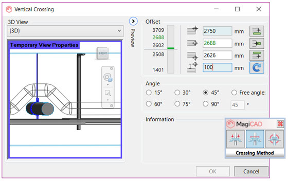
• Generate crossings at one go with smart new functions
• Filter and manage builders work openings more competently
• Workout domestic hot water circulation flow rates
• Workout the time to attain hot water design temperature
• Measure the volume of the piping system
• Compute various design areas all at once in sprinkler design
• Produce custom cable trays in the dataset
• Identify your own circuit numbering rules
• Set up cable packet connections devoid of drawing wires
• Allot sizing methods to duct and pipe segments
• Workout the surface area of ducts and fittings

MagiCAD 2018 Update Release 3 for AutoCAD – Highlights

• New product class: LED stripes
• Workout the time to get to Hot Water Design Temperature
• Determine several design areas and systems concurrently in sprinkler design
• Reproduce text object settings with Create Similar
• Rotate symbols competently while inserting symbols to drawings
• Accumulate and deliver non-model drawings as part of projects
• Update circuit number to all cables

MagiCAD allows MEP design with Europe’s largest product model database, highlighting more than 1,000,000 actual products and product variants from 250 top manufacturers across the world. Each model inside the database is finished with perfect dimensions and wide-ranging technical data. MagiCAD provides localization for different country-specific standards, and it is very popular among contractors and designers in projects in over 70 countries globally.

For more information, visit www.magicad.com​


50 essential AutoCAD Commands

~~~~~~~~~~~~~~~~~~~~~~~~
Published By
Rajib Dey
www.bimoutsourcing.com
~~~~~~~~~~~~~~~~~~~~~~~~

Tuesday, March 13, 2018

50 essential AutoCAD Commands

Autocad: It is 2D or 3D computer supported drafting software program used to make blueprints for buildings, bridges and computer chips and used in architecture, construction and manufacturing.

Operating AutoCAD is depended on some commands and people can create their own set of mostly used commands to normalize in a few steps. Here is a list of only 50 usable commands that can speed up the work game, find new shortcuts or have some easy to use tools to control the project if they forget the commands they need.

1. APPLOAD: it can loads and unloads applications and specifies the applications that need to load at startup. The Startup Suite option loads the specific application whenever the product begins.
2. AREA: the area and perimeter of the certain object are shown at the Command prompt and in the tooltip and the MEASUREGEOM command gives extra measurement options. The BOUNDARY tool can be used to create a closed region and the Properties palette can find the area.
3. Background: while choosing a background image for the work area it can be a solid in color, a gradient in color or an image from the computer.
4. BMPOUT: it is called bitmap file that contains the selected objects made by the users, the file shows what is shown on the screen. Generates a bitmap image or .bmp format after selecting a series of objects, surfaces or regions.
5. BOX: it is used to create box with a specified center point or of sides of equal length or can create a box with length, width and height specifically given.

6. BURST: it expands a block or an object but keeps the qualities same, this is a highly essential tool.
7. CHSPACE: the selected objects are scaled automatically in the new space, objects can be moved from the layout to the model and conversely.
8. CLOSEALL: it opens up all the closed AutoCAD windows and if there are any kind of changes to any files is done which is not saved then this command will ask users to save.

9. COLOR: sets the color for new objects, a layer color can be chosen for future objects, lines and surfaces.
10. DIMALIGNED: shows the In-Place Text Editor that can be used to edit the dimension text and the displayed measurement is represented with angle bracket and a dimension can be created aligned with a circle or arc.
11. DIMBASELINE: it creates a linear, angular or coordinate dimension and the work starts from a baseline of an earlier dimension.
12. DIMRADIUS: it creates a radius dimension for circles and arcs.
13. DIMTEDIT: this command is used to change or restore the location of the dimension line.

14. EDGESURF: creates a mash between four adjoining edges or curves.
15. EXPLODE: breaks a compound object into its component objects while modifying the components separately.
16. ID: shows the coordinates of any point on the worksheet.
17. LIGHT: controls lights and its effects on 3D models.
18. LINETYPE: creates, manages and selects line types.
19. MATLIB: it can import and export materials from and to a library.
20. MLINE: creates multiple parallel lines.
21. MLEDIT: it edits the lines.
22. MULTIPLE: continues next command again and again still stop.
23. MVSETUP: fix the layout of a drawing.
24. OOPS: restores the recent deleted items.
25. OVERKILL: goes through the entire model and deletes the duplicate and overlapping items to make the model smooth.
26. PAGESETUP: defines the page layout and adds more to the plotting device, paper size and other settings for every new layout.
27. PFACE: creates a 3D mesh height by height.
28. PREVIEW: shows the model before printing.
29. PURGE: it deletes unused objects in the drawing through a series of filters.
30. QDIM: after select any object it can create a dimension quickly.
31. QLEADER: creates a leader and a leader annotation fast.
32. QSAVE: it auto saves the file while working and gives a name to the unnamed files.
33. QSELECT: it can select objects quickly as per list of filters.
34. RECOVER: regains a damaged file.
35. RENDER: creates a render of the current model.
36. REVOLVE: makes revolved solids by moving 2D objects around a user defined angle.
37. RULESURF: creates a surface to join two previously defined curves.
38. SAVEALL: automatically saves all drawings.
39. SHOWMAT: shows a set of information for a selected object.
40. SKETCH: makes a series of freehand drawing things.
41. SPELL: checks the spelling.
42. SUBTRACT: creates a region from a solid and region by subtraction:
43. TABLET: adjusts a tablet.
44. TIME: shows a statistics table of the recent file with every time of updating, editing and making.
45. U: undoes the mistakes.
46. UNDEFINE: undoes the deleted command.
47. VPORTS: controls AutoCAD windows for 2D and 3D models.
48. XLINE: makes an eternal line.
49. 3DSOUT: export files consistent with 3D studio.
For more information, go through the following link
 www.archdaily.com

50 essential AutoCAD Commands

~~~~~~~~~~~~~~~~~~~~~~~~
Published By
Rajib Dey
www.bimoutsourcing.com
~~~~~~~~~~~~~~~~~~~~~~~~ 

Wednesday, March 7, 2018

How to generate custom floor patterns in Revit

This revit tutorial provides brief instructions on how to use Revit for producing a custom floor plan with the help of split element and create parts tools.

The following revit shortcuts are used in the tutorial:


UN - Project Units WA - Wall CS - Create Similar RP - Reference Plane Al - Align TR - Trim/Extend AR - Array CO - Copy
In this tutorial, you will learn how to cut up the last layer of the floor and generate custom pattern as well alter the material of various floor tiles.
Split elements: Split elements are used to cut an element (like a wall or pipe) at a specified point, or eliminate a segment among 2 points. In Revit LT 2018, go to the “Modify” menu and opt for the “Split” tool.

There are 2 versions of the Split tool like “Split Element” and “Split with Gap “. Go ahead and choose split element” tool from the drop-down menu. Once it is activated, it should be noticed that the cursor has been changed to an icon of a knife / scalpel blade. Just hover over the element that you want to split and Revit will demonstrate a blue line to specify where the split will be done. Go ahead and left-click with your mouse. Revit then splits the element at this point.

Create Parts: It is possible to create a part from an element that has been chosen in the drawing area, either in the existing project or in a linked model.
In the case of elements containing layers or subcomponents, like walls, individual parts will be generated for those layers. For other elements, a single part element is formed. In either case, the consequential part or parts can then be separated into smaller parts.
To learn how to create the custom plan, watch the following video tutorial.

Read more
~~~~~~~~~~~~~~~~~~~~~~~~
Published By
Rajib Dey
www.bimoutsourcing.com
~~~~~~~~~~~~~~~~~~~~~~~~

Thursday, February 15, 2018

How to create parametric walkway in Revit

In this revit video tutorial, you will be familiar with the necessary steps to model a parametric walkway (twisted looking structure with triangular grid) in Revit.

It begins like a conceptual mass family. You will learn the methods essential for creating model of a spline with triangular profiles at various angles as well as transform it into a form.

Then you will gather knowledge on how to create the model of a curtain panel based family and load it into the mass. Finally, you will learn how the mass is loaded into the project with the addition of a concrete strip at the floor level.

While generating a mass family in the Family Editor, it is possible to load the family into a project, and set instances of the mass family in the project.

Click NewConceptual Mass. In the New Conceptual Mass dialog, opt ofr Mass.rft, and click Open.

The file is available in the following folder:
%ALLUSERSPROFILE%\Autodesk\\Family Templates\\Conceptual Mass


The conceptual design environment opens. The Forms tool and other tools are applied to generate the mass.

In the tutorial, the following shortcuts are used to accelerate the speed of the work.


UN - Project Units
CS - Create Similar
RP - Reference Plane
Al - Align LL – Level

To view the complete processes, go through the following revit tutorial.

~~~~~~~~~~~~~~~~~~~~~~~~
Published By
Rajib Dey
www.bimoutsourcing.com
~~~~~~~~~~~~~~~~~~~~~~~~

Wednesday, February 14, 2018

Tips to improve the Revit Templates

Revit Project Templates provide a beginning environment and standards for new projects and project templates are used as either the default templates or define custom templates to encourage office standards. Besides of giving a beginning point for a new project, a project template also provides view templates, loaded families, defined settings and geometry etc.

After installing Revit software in the system, it opens various templates for different disciplines and types of building projects while users can also create project templates to locate specific needs or to ensure observance to office standards. As Revit has lot of facilities and tools for the users, it has become the favorite one of the architects, designers, project managers, virtual construction modelers and BIM managers.


This article is ideal for the Revit users who want to know more about the Revit Templates and the process to improve their projects and method of work.
Use Templates in files and views: Viewer templates are very useful and the people who work with Worksets find some difficulty to configure the visibility of every Workset. So this template helps to see the limit of views, the appearance of categories, filters and many more; using templates also makes the views standard and make them faster.
1. Use Worksharing: Most of the people are not aware about the templates and still create separate models of a project and then keep them in separate files to join them together, it is a time taking work. In Revit the entire project can be developed and made with the whole team in the same time in a file; where people can do different tasks in a same time like modeling the topography, working with structures, finalizing the architecture, detailing interiors etc. Basically in Revit, people can model an entire project in a same time and can create clash detection to detect the interference.
2. Use Shared Families: When any team works on similar projects with similar benefits and have a group of families that is always together or in toilets or MEP solutions, using the shared-families will unite them all while the editing and measuring can be done separately.
3. Crete Assemblies: The worst thing in detailing things in Revit is making every view and here Montage helps to bring together families of different categories and make a single element with a list of views.
4. Group and organize the views: In Revit, designers can create separate documents, Preliminary Study, Architecture etc. organize them and filter the views as per need.
5. Allot a code for everything: When the subject matter is numeric it is better to organize, parameterize and categorized them as per order like assigning codes; it will help in filtering exactly as per the needs of users.
6. Learning to leader the phases: Phases are one of the smarter things in a project program as it help with ideas, designs and manage the difference between the old and new; also impress the customers and create numeric and tables.
7. Use the Parts: Parts can separate the walls from each other and can help to create wonderful detailed walls with separate structure, finishes, details etc. Users can hide some parts or delete parts to manage the walls.
8. Creating a board: Revit has previously made the families of boards with different sizes but it is better to have a single family of boards with different sizes mean only one family with everything.
9. Purge: As the Revit models are huge, templates help to keep them in order but unnecessary templates are a burden, the Purge command deletes the unnecessary ones.
10. The drawing options: This advantage Draw Options tool allows creating different proposals within the one Revit file.
Article Source: www.archdaily.com.br

Tips to improve the Revit Templates

~~~~~~~~~~~~~~~~~~~~~~~~
Published By
Rajib Dey
www.bimoutsourcing.com
~~~~~~~~~~~~~~~~~~~~~~~~

Monday, February 12, 2018

Tech Soft 3D introduced HOOPS Communicator 2018 Toolkit for BIM & CAD professionals

Tech Soft 3D, leading solution provider for the engineering software industry, just introduced HOOPS Communicator 2018 software development toolkit (SDK). It is a robust toolkit for generating advanced web-based engineering applications.

HOOPS Communicator is now compatible with AutoCAD DWG files and point clouds to facilitate creating architectural, engineering and construction (AEC) or building information modeling (BIM) applications.


Besides, supporting IFC, an interoperable file format for construction is also supported. These tools arrange a strong environment for visualization, query and navigation of construction models.
With HOOPS Communicator 2018, it is possible to make advanced workflows like product lifecycle management (PLM) and product configurators with significant enhancements like the ability to aggregate models. Assemblies can be easily divided into their constituent parts which can be integrated when requested or instantly substituted for several adjustments.

HOOPS Communicator 2018 embraces and simplifies major complications associated with delivering advanced graphics. There are various new features like x-ray rendering mode and ability to employ materials to geometry on the client for superior visual fidelity.

To get more details about HOOPS Communicator, visit techsoft3d.co
Tech Soft 3D introduced HOOPS Communicator 2018 Toolkit for BIM & CAD professionals

~~~~~~~~~~~~~~~~~~~~~~~~
Published By
Rajib Dey
www.bimoutsourcing.com
~~~~~~~~~~~~~~~~~~~~~~~~

Tuesday, February 6, 2018

BricsCAD Shape – A handy tool for designers and architects

Bricsys, the leading developer of cad software, has introduced a new 3D conceptual modeling tool that is specifically designed for architects to improve the speed of their 3D design work.

With this conceptual modeling tool, the architects and engineers can simplify their schematic design work.

The multi-functional “Shape” tool is applied to generate walls, slabs, structural elements and more. Direct modeling features allow you to drag, connect, push/pull and extrude as per your choice. Wall connections are automatically mitered for you.

With BricsCAD, the designer can create their ideas in 3D easily with a series of common architectural components and materials together with straightforward shape generation tools. BricsCAD employs the similar parametric and modeling engine (ACIS) that is found in Bricsys’ BricsCAD Platinum CAD software.

BricsCAD Shape files can be opened directly in Bricsys’ BIM platform, BricsCAD BIM to speed up the BIM workflow. BricsCAD Shape is totally free to use.

It comprises of a library of materials, textures and pre-built 3D components. The included collection of doors and windows can be utilized separately. The users can also generate their own custom versions. Form your model according to your preference with the Visual Styles panel in Shape.

Shape is only compatible with Windows (later on it will work with macOS and Linux). It is necessary for the users to sign up for a Bricsys account and download the program to test it. Not just for this reason, BricsCAD offers more material and library content as compared to the free version of FormIt.
To learn more about BricsCAD Shape, go through the following link blog.bricsys.com

Bricsys introduced Mac OS X version of BricsCAD V18

~~~~~~~~~~~~~~~~~~~~~~~~
Published By
Rajib Dey
www.bimoutsourcing.com
~~~~~~~~~~~~~~~~~~~~~~~~

Tuesday, January 30, 2018

New updates are available for BIMscript, the exclusive content creation solution by BIMobject

New updates are available for BIMscript, a solution for generating digital building products. The updates provide a superior grade of flexibility and features that unveil the solution for improved product configuration for more product categories, along with a larger scope of products having complicated parametrics, and the complete sector of windows and doors.

With BIMscript the users will be able to make their own digital building products, also mentioned as BIM objects.


Users can create parametric, native BIM objects in a series of recognized formats for industry-leading BIM applications like Autodesk Revit, AutoCAD, 3DS, Graphisoft ARCHICAD, and Trimble SketchUp, as well as AR and VR formats. These BIM objects are then gathered on the platform BIMobject Cloud, which act as a Single Source of Truth for its over 650,000 professional registered users and in excess of 1,000 represented brands.
The updates significantly enhance the number of product categories that can be formed. These now comprise of windows, doors, and customizable products. The users get the ability to set the parameters according to their choice rather than selecting among a limited number of preset options.
BIMscript now becomes an established scripting language that contains numerous developed BIM objects. The new updates practically eliminate the few remaining restrictions to what can be scripted. Define any building component you like and receive full support for all market standards throughout the BIM process.

These custom parameters are further used in various intelligent processes to workout, adjust, and produce BIM objects on the basis of the information provided early. The processes improve the user’s workflow both via significant savings in time spent, and through the extra scopes.
The new features will be useful for doors and windows manufacturers as they can access the tools to convert their products into parametric BIM objects. The updated version of BIMscript is free for accredited BIMscript developers.

BIMscript automatically generates several parametric BIM and static formats from a single source of development. This accelerates the formation of various formats by 400% compared to traditional methods. Besides, the solution eliminates the requirement for buying multiple CAD/3D/BIM software for development, as well as the requirement for expert knowledge in several systems, because the making of native formats is accomplished by the BIMobject Cloud. With quick hosting, publishing, maintenance, and version handling, the development processes become protected and manageable.
he BIMobject Cloud can produce BIMscript as a batch process. For static file formats formed with BIMscript, such as IFC, DWG, 3DS, and OBJ, BIMobject also creates a 3D-configurator. The users can configure the object in the BIMobject Cloud and then download the consequential version of the product.
To get more updates on BIMscript, go through this link bimobject.com
New updates are available for BIMscript, the exclusive content creation solution by BIMobject

~~~~~~~~~~~~~~~~~~~~~~~~
Published By
Rajib Dey
www.bimoutsourcing.com
~~~~~~~~~~~~~~~~~~~~~~~~

Monday, January 29, 2018

Datakit announces the version 2018.1 of its CAD conversion tools

The latest update of Datakit’s CAD data exchange software range is now available!
This new version of CrossManager, CrossCad/Plg and CrossCad/Ware adds several improvements to Datakit’s interfaces:
- These applications can now read new versions of CAD formats: SOLIDWORKS 2018, NX 12 and DWG 2018.
- CrossManager is now able to convert 3D models to .prc files. This format allows to encapsulate 3D data in a PDF. Thus, CrossManager enables to integrate models coming from most of 3D formats in a PDF. Conversion to PRC is available from more than 20 CAD formats.
- The Revit format (.rvt files) reading is now available, expanding Datakit’s BIM data conversion offering, begun last year with the IFC format.
This new reader enables software vendors to add Revit import capabilities to their own application by using CrossCad/Ware. It also enables end users to convert Revit files to IGES, STEP, 3DPDF and PRC with CrossManager
A Revit file, converted in 3DPDF with CrossManager. The file can thus be opened in Adobe Acrobat Reader™ to be viewed. The instances list of the original model is accessible.
This new interface is able to read geometrical data along with colors and instances contained in Revit 2017.x files
CrossCad/Ware allows to work from Revit files in third-party applications
This version also benefits from the constant improvement of the dozens of CAD converters provided by Datakit. Indeed, they are maintained constantly, in order to improve their quality and to process new entities, while optimizing the execution time.
Datakit tools remains independent of any external API, so it does not require any third-party license to work.

All formats supported by CrossManager
Users wanting to try Datakit software can download it and get a trial license on CrossManager and CrossCad/Plg official pages.
Software vendors interested in CrossCad/Ware, the API enabling them to integrate Datakit technology in their own applications, can visit the API description page and contact Datakit to get information relevant to their activity.
Source: www.datakit.com
Datakit announces the version 2018.1 of its CAD conversion tools
~~~~~~~~~~~~~~~~~~~~~~~~
Published By
Rajib Dey
www.bimoutsourcing.com
~~~~~~~~~~~~~~~~~~~~~~~~

Thursday, January 18, 2018

progeSOFT SA released progeCAD’s iCADMac 2018 for Mac

Swiss-based progeSOFT SA released iCADMac 2018, a complete and professional 2D/3D DWG-based CAD system that has the ability to read and write AutoCAD files up to version 2018.

This newest version is compatible with Apple’s macOS El Capitan and High Sierra operating systems. The user interface is significantly improved to simplify the working process.

By applying more complete, contextual menus system, time & the numbers of mouse clicks can be saved significantly.

In iCADMac 2018, there are two user interfaces available for the users. The users can choose from either the classic “light grey” theme or the new “dark 2018” theme. With the help of the vector-based icons in the macOS menu architecture, high-resolution 4K displays are possible on Apple’s computers.

There are various new tools contained in iCADMac 2018 which range from a new AutoComplete feature to accelerate typing commands and system variables. SuperHatch generates an area hatch with an image, a block, an external reference, or a wipeout.

There exist new features for managing hatches and gradients. Trimmed hatches stay associative and function as a single entity. With a revamped dialog box, enhancements are also made to print dialogs. New Auto-Hide palettes are used to break down palettes automatically while shifting the pointer away from the palette. Palettes are expanded automatically while moving your pointer back towards them.

To get more information, click here: www.progesoft.com

progeSOFT SA released progeCAD’s iCADMac 2018 for Mac

~~~~~~~~~~~~~~~~~~~~~~~~
Published By
Rajib Dey
www.bimoutsourcing.com
~~~~~~~~~~~~~~~~~~~~~~~~

Friday, December 29, 2017

How to perform quantity takeoff in Tekla with a Revit IFC

In this Revit video tutorial, you will learn how to apply a Revit IFC in Tekla structures to generate a quantity takeoff report.

By doing this, import will go to ad model in the reference models list and look over for that IFC file.


The video will teach you the following lessons :-
1. Import an IFC Model as a reference model.
2. Find out its properties to view IFC object information.
3. Download Tekla Warehouse content that comprises of Organizer categories and templates to be utilized with a Revit IFC.
4. Apply the organizer to create custom reports and accomplish quantity takeoff directly with the IFC.
5. Export information to Excel.

It is possible to import IFC models as reference models and pull out information instantly with the Organizer. Alternatively, the imported IFC objects can be transformed into Tekla Native objects. The imported IFC reference models can also be utilized for clash checking and scheduling.

Read more

~~~~~~~~~~~~~~~~~~~~~~~~~
Published By
Rajib Dey
www.constructioncost.co
~~~~~~~~~~~~~~~~~~~~~~~~~


Tuesday, December 26, 2017

CAD blocks can save huge time & money in your cad design & cad drafting process

CAD blocks are also known as model libraries as well as standard part libraries or just blocks. These CAD blocks can be used to streamline the CAD drafting & designing process. A CAD block belongs to a named object, or group of objects, that is drawn in 2D or modeled in 3D and after that it is used to generate continual CAD content like drawing symbols, standard details, common parts or other objects operated constantly inside a drawing or model.

As for example there may be various doors inside the plan having identical type and size in a customary residential floor plan. CAD blocks are used to reprocess those doors rather than drawing a new one always. This results in saving huge time and money.


Benefits of CAD Blocks

Curtail Iterative Tasks — when the design team requires to utilize an object or part several times in a drawing, they should employ blocks. Blocks will save significant times while generating objects primarily as well as save huge time when modifications are necessary. As for instance, if it is required to modify the type of water closet utilized in all the bathrooms all through the building in a big commercial architectural floor, it is not necessary to modify each water closet one at a time. Just revise the block in Block Editor and the block will be automatically corrected in every allocated space in the drawing.

Accuracy — If you use a perfect CAD part or block, apply that similar CAD part or block all through a drawing or model. It will maintain reliability and reduce prospective errors originated from redrawing the item every time. Besides, if you are going to start the design with complicated parts, just download the required part or model directly from a manufacturer or supplier. Thus, you will get proper size and specification information to apply in your design.

Reduced File Sizes — File size is decreased through instancing content devoid of redefining object data for each instance, a block is applied. Just use your CAD program to obtain the insertion point and rotation by reprocessing the object geometry out of the original block. It can greatly optimize the performance while dealing with large projects.

Maintain Consistency — If you contain a series of CAD standards, make sure that all the drawings and models are perfectly demonstrated. If all your title blocks, plumbing fixtures, piping symbols and fasteners are shown systematically from one drawing to another, apart from which CAD user operated on them, it is a very crucial factor in improving the effectiveness as well as and minimizing the chances for error in your drawings.

Block Attributes — There are various types of metadata information known as attributes in the blocks. These may range from information like title block information, asset tracking numbers, or manufacturer information for example part number, model or weight. This data can be associated with an Excel database and extracted to generate reports, bills of material and schedules.


CAD blocks can save huge time & money in your cad design & cad drafting process


~~~~~~~~~~~~~~~~~~~~~~~~
Published By
Rajib Dey
www.bimoutsourcing.com
~~~~~~~~~~~~~~~~~~~~~~~~

Saturday, November 4, 2017

ARES Kudo – The newest cloud based cad application

Graebert GmbH, the leading developer of high-performance CAD software across desktop, mobile and cloud, launched ARES Kudo, a completely brower-based DWG editor.

The users can avail all the features ranging from dynamic blocks to associative dimensioning, printing, xrefs and line commands in their browser.


ARES Kudo performs as the “hub” for all DWG drawings. Users will be able to relate their current cloud-storages (which comprise the most recognized solutions like Box, Dropbox or Google Drive). The software provides vertical, industry-specific solutions. The users can avail drawings which are preserved on the servers of Onshape.

ARES Kudo facilitates the users to connect with various types of cloud storages and locate DWG files in all of them at the same time, prior to opening file with intention of viewing and editing.

ARES Kudo empowers the owner of the DWG file to get a constant perception concerning who has given access to any particular file. With ARES Kudo, it is possible to allocate drawings with co-workers and ensure everybody is dealing with the latest version as well as allotting view-only rights to choosing partners or customers.

Given below, some exclusive features of the software :-
a. View, annotate and edit on numerous devices with desktop, web or mobile apps irrespective of whether you’re connected or not.
b. One platform for drawing, annotating, viewing, and sharing
c. No check-in / check-out. Everyone with privileges will be able to edit all together.
d. Implant various design options inside a single drawing for instant feedback.
e. Connect annotations, discussion threads and task lists to locations in your drawing.
To download a trial version, click on the following link http://bimoutsourcing.com/ares-kudo-the-newest-cloud-based-cad-application.html

ARES Kudo – The newest cloud based cad application

~~~~~~~~~~~~~~~~~~~~~~~~
Published By
Rajib Dey
www.bimoutsourcing.com
~~~~~~~~~~~~~~~~~~~~~~~~