adsense analytic

Friday, March 31, 2017

How To Use AutoCAD For Making Roof With Sloping Parapet

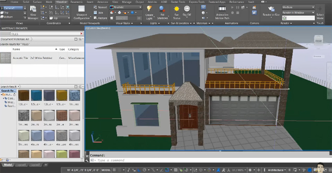
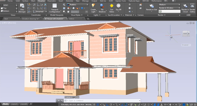
This exclusive autocad video tutorial is presented by Sabeer cad. The video will introduce step-by-step procedures for producing a roof that contains sloping parapet on top of the double storied house.
A gable roof, alias pitched roof or peaked roof, is a roof shape that is mostly recognized all through the globe where the weather is cold or moderate. It includes two roof sections sloping in opposite directions and arranged in such a way that the uppermost, horizontal edges coincide to develop the roof ridge. Here the roof design is made with rafters, roof trusses or purlins. The pitch of the roof and the height of the gutters differ significantly.
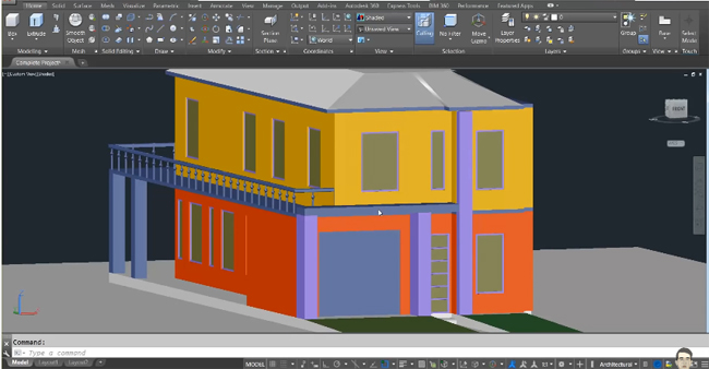
One can use different types of roof commands in AutoCAD to generate various types of roofs, from easy to complicated shape and from flat to sloped. As soon as the roofs are formed, they can be altered by modifying their heights and slopes.


How to use AutoCAD for making roof with sloping parapet

~~~~~~~~~~~~~~~~~~~~~~~~
Published By
Rajib Dey
www.bimoutsourcing.com
~~~~~~~~~~~~~~~~~~~~~~~~

Thursday, March 30, 2017

How To Use IES Light In V-Ray For Revit

This video is created by Chaos Group that shows how to apply lights (IES lights) in V-ray for Revit.
IES light type is applied to load and render naturalistic light distribution profile files (IES files). The icon is available in the V-Ray main toolbar.
V-Ray for Revit is compatible with IES lights in the project. If the IES light files are untraceable in any of the search paths in v-ray, it applies a generic IES file that lusters light uniformly in all directions.
An IES file refers to a text file that defines the depth of a light source at points on a spherical grid. It offers more photorealistic lighting effects in rendered images as compared to other types of light distribution.
V-Ray for Revit facilitates to enable and disable light groups in the Revit. Light groups are obtained by selecting the Rendering Settings in the view properties of the view to be rendered, and clicking on the ‘Artificial Lights’ button. This button is activated if the lighting scheme is arranged to a mode with artificial lights allowed.


How to use IES light in V-Ray for Revit


~~~~~~~~~~~~~~~~~~~~~~~~
Published By
Rajib Dey
www.bimoutsourcing.com
~~~~~~~~~~~~~~~~~~~~~~~~

Wednesday, March 29, 2017

How To Draw Structural Slab In Autodesk Revit 2017

Inside this autodesk revit 2017 video tutorial, you will master the detail about how to to draw structural slab in autodesk revit structure 2017. This video lets you operate an expert drawing by browsing some of the Autodesk revit tools.

This tutorial generally comes up in two ways. First up, using a structural tool for modeling of a floor slab in structure menu and the second part comes with the floor designing.


In this tutorial the tool that is mostly used to create rectangular blocks is boundary line. The entire demonstration is presented in 3D also.
Now enjoy the video tutorial which is proudly presented by Cefci Civil Engineering.


How to Draw Structural Slab in Autodesk Revit 2017

~~~~~~~~~~~~~~~~~~~~~~~~
Published By
Rajib Dey
www.bimoutsourcing.com
~~~~~~~~~~~~~~~~~~~~~~~~

Tuesday, March 28, 2017

Some Useful Tricks For Using Solid Editing Tools In AutoCAD 2017

This autocad tutorial will teach you how to use fundamental editing tools in AutoCAD 2017 for performing precise solid modeling. By watching this video, one will be familiar with different types of solid editing tools like subtract, slice and others.
3D solid editing tools are accessible in the solid editing ribbon panel.
Solid modeling is a process for describing 3d objects as solid forms. While creating a 3d model with solid modeling, fundamental forms (boxes, cones, cylinders etc.) of your model are started. These fundamental forms are known as primitives.
The solid editing tools can be accessed by applying a single AutoCAD command known as Solidedit. One can apply the undo option to undo the last solidedit option that has been already applied devoid of existing the command.


Some useful tricks for using solid editing tools in AutoCAD 2017


~~~~~~~~~~~~~~~~~~~~~~~~~~~
Published By
Rajib Dey
www.bimoutsourcing.com
~~~~~~~~~~~~~~~~~~~~~~~~~~~

Monday, March 27, 2017

How To Use V-Ray Material Editor To Produce And Edit Materials In Revit

Chaos Group presents an exclusive video tutorial for the Revit users. The tutorial provides step-by-step guidelines on how to utilize the separate V-Ray Material Editor to generate and edit materials in Revit.
For more detailed information, go through the following link docs.chaosgroup.com
The V-Ray Material Editor can be used to generate, edit, and save several materials into a .vismat or .vrmat file to be opened by other scenes.
The V-Ray Material Editor contains the following :-
Material preview – A preview render that demonstrates the look of the adjusted material. As soon as a material preview is created, the preview image is reserved for future application.
Preview – Updates the material preview.
Save – Saves the existing material(s) to a .vismat file overwriting the files which exist beforehand.
Save As – Opens a dialog to identify the position of the material(s) to be saved.
Live update – If it is turned on, the material preview will automatically update each time with the modification of one of the material properties.
Save on close – Automatically saves the modifications applied to the materials to a .vismat file as soon as the editor is closed.
Materials List – A list of all materials in the existing .vismat or .vrmat file. It is possible to generate new materials, import materials from file, rename materials, and delete them.
Material options – All the available options for the currently selected material.


How to use V-ray Material Editor to produce and edit materials in Revit

~~~~~~~~~~~~~~~~~~~~~~~~~
Published By
Rajib Dey
www.bimoutsourcing.com
~~~~~~~~~~~~~~~~~~~~~~~~~

Friday, March 24, 2017

AutoCAD 2016 Tutorial On Cameras, Materials, Lighting And Rendering

Learn the detailed process for creating a 2d house plan as well as 3d model of the house with the use of AutoCAD by going through this AutoCAD video tutorial.


The video sheds light on the following topics :-
Generating Cameras
Using Materials
Lighting
final Preview of the project
In this tutorial, AutoCAD 2016 is used.


AutoCAD 2016 Tutorial on cameras, materials, lighting and rendering

~~~~~~~~~~~~~~~~~~~~~
Published By
Rajib Dey
www.bimoutsourcing.com
~~~~~~~~~~~~~~~~~~~~~~

Thursday, March 23, 2017

How To Use Revit 2017 To Make A Great Elevation

This Revit video tutorial demonstrates how to use Revit 2017 to produce a perfect and clear elevation in Revit.
Revit 2017 contains a new feature that is called elevation and section depth cueing. The revit users now will be able to set a distance fade in Section and Elevation Views in Revit.
Depth cueing can be used for modeling elements and graphic display effects like shadows and sketchy lines. The feature is not suitable for annotation elements, line weight, linework, background image, or background color.
Once depth cueing is applied to a view, the following can be performed :-
 Export the view to an image file.
• Print the view (raster processing only).
• Add the view to a sheet.

How to use Revit 2017 to make a great elevation

~~~~~~~~~~~~~~~~~~~~~~
Published By
Rajib Dey
www.bimoutsourcing.com
~~~~~~~~~~~~~~~~~~~~~~

Tuesday, March 21, 2017

How To Complete An Advanced House Project With AutoCAD

The beginner’s AutoCAD users, who want to sharpen their 2D and 3D modeling skills, can watch this AutoCAD video tutorial. The video shows how to complete an advanced house project with AutoCAD. The AutoCAD users can learn how to generate a 2d house plan by using different types of commands.


Given below, the lists of commands which are used in this project.
a. Settle drawing units and limits
b. Specifying area of your drawing
c. Creating walls, windows and door
d. Applying line Command
e. Applying rectangle fillet champher
f. Creating layers in Autocad and process of using them
g. Applying design center in Autocad 2016
h. Generating dimensions for you drawing
j. Creating elevation from any 2d plan
i. Accomplishing 3d Modeling of the 2d Plan with explanation

How to complete an advanced house project with AutoCAD

~~~~~~~~~~~~~~~~~~~~~~
Published By
Rajib Dey
www.bimoutsourcing.com
~~~~~~~~~~~~~~~~~~~~~~

Monday, March 20, 2017

How To Create A Pot Plant With AutoCAD

This is another useful tutorial from Mufasu Cad.

The tutorial is specifically designed for beginner cad modeler to make their drawing practice exercise better.

The tutorial will briefly demonstrate the process for creating a pot plant.

Download Autocad 2017


How to create a pot plant with AutoCAD


~~~~~~~~~~~~~~~~~~~~~~
Published By
Rajib Dey
www.bimoutsourcing.com
~~~~~~~~~~~~~~~~~~~~~~


Sunday, March 19, 2017

Brief Overview Of Connections In Revit 2017

This Revit video is created on the new feature of Revit 2017 in the structure ribbon inside connections.
In Revit 2017, there are 22 structural connection types into the product which are acquired from the Autodesk Advance Steel product directly. Now, the structural consultants will be able to show the objective of design inside a steel frame to make communication in a superior manner with the client and the fabricators.
Besides, initial design coordination will be accomplished by modelling items like haunches and gusset plates with may create the scope of clashing with other elements.
The connections are designed to EC3 and directly select design loads from the results of an analysis which are preserved inside Revit.

Brief overview of connections in Revit 2017


~~~~~~~~~~~~~~~~~~~~~~
Published By
Rajib Dey
www.bimoutsourcing.com
~~~~~~~~~~~~~~~~~~~~~~


Friday, March 17, 2017

How To Use AutoCAD To Design 2D And 3D Mechanical Idler Plate

This AutoCAD tutorial is specifically designed for mechanical engineer that demonstrates the detailed process for creating the design of 2d and 3d Idler Plate by applying some simple commands.

AutoCAD Mechanical design and drafting software contains extensive libraries of standards-based parts and tools which can be used for performing standard mechanical CAD tasks automatically as well as speeding up the mechanical design process.


The most updated version is AutoCAD Mechanical 2017 that includes the following features :-
1. Support for international drafting standards
2. Autodesk Synergy for mechanical engineering
3. Smart mechanical engineering dimensions
4. Associative balloons and bills of materials (BOMs)
5. Power dimension in-place editor
6. BOM migration.


How to use autoCAD to design 2D and 3D Mechanical Idler Plate


~~~~~~~~~~~~~~~~~~~~~~
Published By
Rajib Dey
www.bimoutsourcing.com
~~~~~~~~~~~~~~~~~~~~~~

How To Model Reinforced Concrete Structures In Revit 2017

This is a useful Revit video tutorial that demonstrates how to use Revit 2017 for modeling of reinforced concrete structures.
Revit 2017 is ideal for structural engineers as it can produce superior level of details for reinforcement modeling and documentation.
Revit 2017 contains the useful features called Reinforcement connectors and these are family-based and fully customizable, and can meet the needs of each team member. Rebar connectors combine with the rebar that they are connected with, facilitating change management.
Structural engineers apply schematic connectors to explain their needs. Detailers use them to generate shop drawings. Manufacturers can check the complete detail, accurately modeling and representing reinforcement connectors to produce installation instructions. It is possible to include the connectors to groups, assemblies, and partitions with distinctive coupler numbering, and export them to different formats.
Download all Revit materials on BIM standard version 2.0 knowledge.autodesk.com


~~~~~~~~~~~~~~~~~~~~~~
Published By
Rajib Dey
www.bimoutsourcing.com
~~~~~~~~~~~~~~~~~~~~~~