adsense analytic

Showing posts with label Articles. Show all posts

Friday, July 28, 2017

Autodesk Revit 2018 Architecture Fundamentals - Imperial (1st Edition) – An exclusive reference book for Revit users

The Autodesk Revit software is a powerful Building Information Modeling (BIM) program that works the way architects think. The program streamlines the design process through the use of a central 3D model, where changes made in one view update across all views and on the printable sheets.

Autodesk Revit 2018 Architecture Fundamentals - Imperial (1st Edition) is an exclusive reference book for Revit professionals that briefly focuses on the Autodesk Revit functionality to be applied efficiently during the design process.

Initially, the book explains the user interface and basic drawing, editing, and viewing tools. Then you will be familiar with design development tools together with how to model walls, doors, windows, floors, ceilings, stairs and more. At last, you will be introduced with the processes to transform the model to the construction documentation phase.
The book will facilitate the students to generate complete 3D architectural project models and arrange them in working drawings.
The book includes the following topics :-
• Perception of the objective of Building Information Management (BIM) and how it is used with the Autodesk Revit software.
• Administering the Autodesk Revit workspace and interface.
• Dealing with the fundamental drawing and editing tools.
• Generating Levels and Grids as datum components for the model.
• Making a 3D building model involving walls, curtain walls, windows, and doors.
• Inclusion of floors, ceilings, and roofs to the building model.
• Generating component-based and custom stairs.
• Inclusion of component features like furniture and equipment.
• Arrangement of sheets for plotting with text, dimensions, details, tags, and schedules.
• Production of details.

Click on the following link to download the book www.ascented.com

Autodesk Revit 2018 Architecture Fundamentals - Imperial (1st Edition) – An exclusive reference book for Revit users


~~~~~~~~~~~~~~~~~~~~~~~~
Published By
Rajib Dey
www.bimoutsourcing.com
~~~~~~~~~~~~~~~~~~~~~~~~

Wednesday, July 19, 2017

How to use Revit to produce rebar shape images

In some versions of Revit, it is possible to include an image to a family instance or type by using the “Image” or “Type Image” parameter.

Toward Rebar families specific there exist the “Shape Image” parameter, which allow to generate well formatted rebar bending schedules along with the rebar shape image.

Revit provides Rebar Shapes as per the local requirements and codes for various global countries. These Rebar Shapes don’t include these Shape Images so the users get the ability to customize this.

For rebar schedule demonstrations throughout demos of “Rebar with Revit”, I edited the default rebar shape families can be edited and the shape code images can be included to the Shape Image parameter by adhering to BS8666 : 2005. This can produce nice formatted bending schedules for a simple reinforced concrete tunnel.

One can download the content applied for this small model from below:
Rebar Shape Families with Shape Images according to BS8666:2005: Download here (§autodesk.box.com)
 Shape Code Images according to BS8666:2005 : Download here (§autodesk.box.com)

How to use Revit to produce rebar shape images


~~~~~~~~~~~~~~~~~~~~~~~~
Published By
Rajib Dey
www.bimoutsourcing.com
~~~~~~~~~~~~~~~~~~~~~~~~

Thursday, July 6, 2017

BIMcollab ZOOM – The newest model view for BIM professionals

BIMcollab is a user-friendly and robust issue tracker in the cloud devoted to BIM. Issues in BIMcollab are directly associated with positions and objects in your model which can be through browsers or directly from your BIM application. It is still in beta testing phase.

BIMcollab's issue management can preserve, distribute and managing issues in an organized manner. But the most point is that one can get the information where it's required directly inside your BIM tool.

It is a model viewer that is used for generating a federated model out of numerous IFC files for the purpose of evaluating the data in the models. The data can be verified through smart filtering and color-coding against an IDM (Information Delivery Manual).
New features
• Software retitled into BIMcollab ZOOM.
• Introduction of Smart Views.
• Inclusion of Default Smart.
• License activation included (free activation key).
• Choose all elements (Ctrl/Cmd+A) for selection set, coloring, etc.
• Edit prefix for various models simultaneously.

One can download the installers for Mac or Windows and read about the release history, bugfixes and other news. When a new version will be launched, notification will be sent through email.


For more information, visit www.bimcollab.com

BIMcollab ZOOM – The newest model view for BIM professionals

~~~~~~~~~~~~~~~~~~~~~~~~
Published By
Rajib Dey
www.bimoutsourcing.com
~~~~~~~~~~~~~~~~~~~~~~~~

Wednesday, June 28, 2017

QCAD 3.9.1 – A powerful CAD program for performing CAD drafting in 2d

RibbonSoft is the developer of QCAD, an uncomplicated 2D CAD system for everybody. The most updated version is 3.9.1. This CAD based software is compatible with windows, linux, unix and Mac platform.

With QCAD, the CAD users can perform computer aided drafting in two dimensions (2d).
The QCAD facilitates the users to generate different types of technical drawings like plans for buildings, interiors, mechanical parts or schemas and diagrams. The source code of the QCAD community edition is launched under the GPL (Open Source).
Modularity, extensibility and portability are some of the exclusive features of QCAD. The interface of QCAD is very user-friendly.
Given below, some exclusive features of this CAD software.
• Layers
• Blocks (grouping)
• 35 CAD fonts comprised
• Metrical and Imperial units
• DXF input / output
• Printing to scale
• More than 40 construction tools
• More than 20 modification tools
• Construction and modification of points, lines, arcs, circles, ellipses, splines, polylines, texts, dimensions, hatches, fills, raster images
• Different types of strong entity selection tools
• Object snaps
• Measuring tools
• Part library with over 4800 CAD parts
• Scripting interface

To download a trial version, click on the following link. QCAD

QCAD 3.9.1 – A powerful CAD program for performing CAD drafting in 2d


~~~~~~~~~~~~~~~~~~~~~~~~
Published By
Rajib Dey
www.bimoutsourcing.com
~~~~~~~~~~~~~~~~~~~~~~~~

Tuesday, May 30, 2017

New Updates For AutoCAD 2017 For Mac And AutoCAD LT 2017 For Mac From Autodesk

Autodesk has made a significant update to the AutoCAD for Mac product line, which comprise AutoCAD 2017 for Mac and AutoCAD LT 2017 for Mac.
New Touch Bar Support: Touch Bar support for the latest and popular MacBook Pro laptops is included in version AutoCAD 2017.1.
There are three major updates in AutoCAD version 2017.1 which contain the Touch Bar support, user interface improvements and migrating settings functionality.
With Touch Bar support options, the users can get access to turn on and off items like the grid, snaps, object snap tracking, as well as the command line window. It is a very light-handed approach.
The new Autodesk support for the MacBook Pro’s new Touch Bar comprises of default support for 10 functions which can be pulled as a set to the Touch Bar interface. The users will be able to modify this arrangement by inserting from a list of approximately half a dozen other controls to substitute in. There are various features like ISO plane, Object Snap Tracking, Grid On/Off, Dynamic UCS, Snap Mode, and Command Window for adjusting the Touch Bar while operating AutoCAD 2017.1 for Mac or the LT version on a MacBook Pro.
There are other significant UX/UI features like the new abilities to dock and undock the Layers palette and the Properties inspector. This will provide huge benefits to the users who are applying AutoCAD for Mac on two monitors and apply them in a way where the drawing window is arranged on one screen and the palettes on another.
Another significant feature is the improvement to the settings dialog. Now the Users will be able to pass their custom settings to future updates and no longer lose these upon doing so.
With great customization skills, the users get the ability to include or eliminate items from both standard pull down menus and the Tool Sets Palette.
To learn more about Autodesk AutoCAD 2017 for Mac and AutoCAD LT 2017 for Mac and the updates available visit here. For information on the AutoCAD for Mac product line visit here.

To get more information, click on the following link architosh.com

New updates for AutoCAD 2017 for Mac and AutoCAD LT 2017 for Mac from Autodesk


~~~~~~~~~~~~~~~~~~~~~~~~
Published By
Rajib Dey
www.bimoutsourcing.com
~~~~~~~~~~~~~~~~~~~~~~~~

Friday, May 19, 2017

Heritage BIM Is Ideal For Documentation And Development Of Historical Structures

The application of Building information modeling (BIM) becomes more versatile when it offers huge benefits in the documentation and development of historical structures in a system known as historical BIM (HBIM). The process is complicated for transforming point clouds into a 3D model as there are lots of asymmetrical geometries in the concerned buildings. So, various semi-automatic parameterization tools are required.

Historical building information modeling (HBIM) stands for a semantic-aware database of historical buildings, through which the geometric model is associated with explanatory multi-source information. Historical buildings generally comprise of stratified artifacts along with non-regular and complicated geometry, contrasting to present constructions which normally contain regular geometry. Reality-based spatial data that is generated from cutting-edge geomatics 3D modelling methods can deliver a perfect replica of those buildings, containing all the related information, even though the diversified characterizing shapes are a big challenge at the time of modeling the geometry. Often these shapes are remodeled by hand, as there are limitations for impressive automatic recognition. The aims, structure and scale – and consequently the projected level of detail of the model – significantly impact the system to data acquisition (sensors, accuracy) and data processing.

The workflow for HBIM projects commence from data procurement from different sensors in relation to the necessity of context and the projected outputs. Then, the surveyed point clouds should have been pre-processed and curtailed with different systems and standalone software, and possibly modified for segmentation by means of automatic or semi-automatic object recognition into a BIM platform. Besides, elements are modeled and transformed into an approximation of reality in line with parametric rules, so it is likely to adjust each illustration of the model. As a final point, the shapes and the identities of objects should be associated with proper and sound relationships in accordance with the semantic definition of entities. After this, the model is ready to be explored with other information for analysis and monitoring over time. On the other hand, the manual creation of 3D models linked to as-built BIM is complicated and laborious. As the costs and skills necessary for manipulating the data signify that this approach is not justifiable and more automatic or semi-automatic tools for parameterization of metric and non-metric information are essential.

BIM platforms come up with some standalone embedded tools or plug-ins toward 3D modellers, viewers, analysers. They facilitate the best use of point cloud and processing with the intension of generating geometric modelling, feature extraction and parameterization in heritage buildings. Some commercial ones comprise of ArchiCad BIMx by Graphisoft, Scan-to-BIM by IMAGINiT, Revit by Autodesk, BIM360 by Autodesk, Recap by Autodesk, PonitSense by FARO, Leica CloudWorx, Green Spider, Bentley MicroStation V8i and Tekla Structures. Some open-source alternatives are Edificius, Tekla BIMsight and Autodesk Navisworks Freedom by IMAGINiT.


To read the complete article, go through the following link gim-international.com

Heritage BIM is ideal for documentation and development of historical structures

~~~~~~~~~~~~~~~~~~~~~~~~
Published By
Rajib Dey
www.bimoutsourcing.com
~~~~~~~~~~~~~~~~~~~~~~~~

Future Construction Project Should Rely On 3 P’s Of BIM (People, Process & Policies)

To reap the complete benefits of BIM for next generation of construction, the emphasis should be given on the 3 ‘Ps’ of BIM i.e. people, process and policies.
People is the first ‘P’ of BIM: To implement BIM in a positive manner, the organization should need the entire team to realize its significance and accept it’s adaptability. The people are mostly responsible to bring in the advancement and so it should be given first priority against the processes and policies.
It is very crucial to develop sound relationships with professionals, in-house teams or a design support solutions provider. It is considered as one of the most vital factors while commencing technological conversion.
Process is the second ‘P’ of BIM: Sometimes, it is found that even skilled AEC professionals find it difficult to execute BIM though they are fully conscious concerning the benefits of the BIM. They mostly prefer to adopt the shortest and simplest method by employing the new technology with old processes. They give priority to use the obsolete processes because they are accustomed and comfortable with them.
As for instance, it is found that professionals or AEC firms using a building program in Microsoft Excel on one monitor, and although, they require Autodesk AutoCAD or Revit. They are engaged in generating and regenerating the data while they can employ Excel-to-Revit tools and produce spaces from Excel in Revit automatically. Lots of processes produce a lot of data waste over the lifespan of construction projects.
The third ‘P’ of BIM is policies: While going to adopt BIM-friendly processes, company policies are considered as the major barrier to overcome.
BIM becomes effective when all the people, who are associated with the construction project, can distribute information without restrictions as well as collaborate. Contracts generally prohibit information distribution by adhering to the clause of confidentiality, liability and litigation concerns. So, it is vital to understand that design solutions are essential to the protect companies as well as inspire them to collaborate.
Companies can also safeguard themselves with the use of filters to the information they distribute; as for instance, building plans should be marked with green, yellow, or red, to specify whether the information is final, provisional, or incomplete. By making collaboration with stakeholders, all parties can mutually settle definitions, processes, policies, and parameters before the commencement of any project. This initiative can minimize risk and at the same time reorganize the workflows that BIM depends upon.

Article Source : www.pbctoday.co.uk
Future construction project should rely on 3 P’s of BIM

~~~~~~~~~~~~~~~~~~~~~~~~
Published By
Rajib Dey
www.bimoutsourcing.com
~~~~~~~~~~~~~~~~~~~~~~~~

Sunday, March 19, 2017

Brief Overview Of Connections In Revit 2017

This Revit video is created on the new feature of Revit 2017 in the structure ribbon inside connections.
In Revit 2017, there are 22 structural connection types into the product which are acquired from the Autodesk Advance Steel product directly. Now, the structural consultants will be able to show the objective of design inside a steel frame to make communication in a superior manner with the client and the fabricators.
Besides, initial design coordination will be accomplished by modelling items like haunches and gusset plates with may create the scope of clashing with other elements.
The connections are designed to EC3 and directly select design loads from the results of an analysis which are preserved inside Revit.

Brief overview of connections in Revit 2017


~~~~~~~~~~~~~~~~~~~~~~
Published By
Rajib Dey
www.bimoutsourcing.com
~~~~~~~~~~~~~~~~~~~~~~


Monday, February 9, 2015

Some significant features of AutoCAD 2015

AutoCAD 2015 contains some advanced features which can streamline your cad modeling process significantly. These advanced cad features range from an improved user interface and some powerful functionalities.

Some synopsis of the key features:-

  • The key tools become more user friendly with modifications to the Ribbon,
  • Text can be easily maneuvered as well as maps & geographical information can be easily incorporated.
  • Improved user interface and object manipulation will make the design process better.
  • AutoCAD 2015 is enriched with the addition of tools like lasso compatible with other platforms.
  • Superior cloud connectivity and a wide array of licence options.

New features in detail:-

Interface: AutoCAD 2015 contains new user interface and a New Tab replacing the welcome screen. Now it becomes easier to shift between screens. The color scheme is modified to make the text, fine lines and buttons easily visible. Now it is possible to revert to the 2014-and-before ‘light’ color scheme in the ‘Window Elements’ menu. Other significant changes are modifications to the command line function with the inclusion of autocorrect. If you provide any wrong command, you will not receive an ‘unknown command’ error message and at the same time the command will be autocorrected to the most identical exact command.

Preview function: There exists a preview function similar to the commands like ‘fill,’ ‘offset,’ ‘fill it,’ and ‘chamfer.’ Now users can explore with various moves beforehand devoid of committing to anything. A new command preview featureis also available. The results of commands like Trim, Extend, Lengthen, Break and Matchprop will be visible prior to can be viewed choose objects for applying them. This reduces the dependence on undo functionality.

Imaging: There are some new imaging features ranging from plotting, image control and image capture. The users will be able to obtain online maps as static images, control brightness and contrast as well as overlay designs onto them and then print the result to paper, web or PDF.Reality capture is another exclusive feature in AutoCAD 2015.

Point cloud: While sending any images into AutoCAD 2015, the users can add Point cloud and scan files to AutoCAD drawings. AutoCAD depends on geographic data to place the point cloud proportionate to the drawing. If the model contains GPS coordinates, it can be easily traced and overlaid with online maps. Once a point cloud file is added, it can be chosen to avail the Point Cloud Contextual Ribbon. Some several crucial updates included to this like new colorization options based on elevation or classification, scan color, object color and more. Now the users can map and envisage geological shapes as well as others easily and efficiently.

Ribbon improvements: With Ribbon improvements, the Ribbon is upgraded to cope up the new color scheme and offer smooth access to tools. The users can now view and put in blocks directly from the Ribbon for block definitions preserved in the current drawing, as well as comprise galleries for styles which are characterized in the drawing. This offers huge benefits to deal with minor drawings and facilitates to retain only the most applicable blocks loaded into the drawing. With the Mac version, the users can get dynamic blocks and get rid of applying various static blocks. Enhancement with visibility of UI elements like the UCS icon, ViewCube, Navigation Bar and Layout tabs as well.

Graphics: AutoCAD 2015 includessuperior graphics. Linesmoothing purifies wireframe images, so that 2D elements seem to be smoother, particularly when they’re exposed at an angle. Controlling 3D Orbit becomes easier as the users can disable ‘Enable Orbit Auto Target’ in the 3D Orbit menu, afterward click and hold the cursor for identifying the pivot point.

Lasso: The ‘Lasso’ function is based onto the old functionality. In order to apply it, click and drag the cursor to lasso irregular shapes. To apply AutoCAD’s customary rectangular tool, click and release the cursor.

Viewpoint Controls: There are new viewpoint controls. The users can get the ability to resize model space viewports by dragging on their boundaries and the dynamic viewport is more evidently demarcated with a light blue boundary. In order to divide a viewpoint, press CTRL and drag. Alternatively, the users can eliminate a viewpoint by dragging its boundary to the border of the screen.

Mtext: The users can provide bullets and number automatically with New MText features. AutoCAD automatically deals with switching case if the users press Shift while Caps Lock is down, and subscript and transcript can be easily executed with new buttons on the Text Editor Ribbon. With Match Properties inside Mtext Editor, MText properties can be easily copied. The fractions are also made easier - just type a forward slash and AutoCAD will do the rest. There also exists a new Text Align function to align numerous single-align text objects. Text Align is used to align one set of text with another.

Select object: If the users place the cursor over an object, its geometry will show thicker and will divergence with the background, becoming light in case of dark background chosen or dark for the light background. The color will also be modified, if hardware acceleration is switched on the object.

Once the object is chosen, it will show thicker and its color will be changed to ensure that it has been chosen. The grip point is still observable. Whether in 2D or 3D this enhancement facilitates maneuvering objects efficiently in AutoCAD 2015.

Some significant features of AutoCAD 2015

Image Courtesy: getintopc.com

~~~~~~~~~~~~~~~~~~
Published By
Rajib Dey
~~~~~~~~~~~~~~~~~~

Monday, February 2, 2015

Benefits of BIM for Civil Engineers

BIM is mostly recognized in architecture and construction field but its usages are limited to civil engineering field. The civil engineers (who deal with roads & highways designs) are still very much unaware to reap the benefits of BIM completely. To some extent, it is used by civil engineers who perform with structural as well as architectural engineers on a regular basis.

Now the question is what benefits BIM provide to a civil engineer – superior designs and improved efficiency and productivity. With BIM, the civil engineers will be able to decrease the time to a great extent necessary for assessing various alternatives, carrying out alterations as well as generating construction documentation as design and construction documentation are intensively associated with BIM. Consequently, any project can be finished quickly by maintaining anticipated time schedule. The roadway optimization is also improved with the inclusion of simulation, visualization and analysis to the design progression. The following two factors are vital to accomplish a best possible roadway design.

Construct-ability: Usually civil engineers create their design for code compliance, giving less importance to constructability. Belated schedules, change orders and RFI may occur after the commencement of construction, if design is executed imperfectly in the field owing to confusing documentation. While developing a new roadway construction project containing interchanges and bridges with an estimated budget of $100 million, almost 7 to 8 percent of it will be incurred in design development. If the design expense is minimized by 35 percent through a more productivity procedure, $ 2.6 million can be saved. However, if the construction part is decreased by 15 percent with construct-ability throughout the design progression, nearly $14 million can be saved.

Road safety: Normally, sight distance analysis is derived from mathematical equations addressing vertical curvature in the road profile. But, we often, do not include the factors like visual obstructions and horizontal layout by applying this method. So, civil engineers incorporate interactive visualization together with sight distance simulation into the design method because it facilitates them to recognize whether the road geometry congregates vital safety parameters regarding sight distance like curvature, grades as well as visual obstacles like barriers, foliage and berms.

Benefits of BIM for Civil Engineers

Image Courtesy: www.rvwconsulting.co.uk
Ref: www.revitmodelingindia.com


~~~~~~~~~~~~~~~~~~~
Published By
Rajib Dey
~~~~~~~~~~~~~~~~~~~

Wednesday, January 14, 2015

Some industry recognized BIM terms to execute a BIM project

With the advancement of Building Information (BIM), several new technical terms and keywords are included in it. But these BIM terminologies may not be always understandable by the professionals associated with construction industry. Given below the extensive lists of some useful BIM terminologies and their descriptions.

1. 4D, 5D, 6D, 7D: BIM gradually evolves from 2D CAD to 3D CAD. Now there are additional dimensions which are used for connecting the BIM model intelligently with time, cost, and schedule-related information. BIM can integrate 4D (time) and 5D (cost) virtual modeling of buildings, and all facets of life-cycle facility management (6D).

2. Asset Information Model (AIM), Building Information Model (BIM), Project Information Model (PIM): Besides, Building Information Model, there exist Asset Information Model (AIM) and Project Information Model (PIM). An Asset Information Model (AIM) refers to a model that accumulates the data & information required to support asset management i.e. for the operation of an asset. ‘Asset’ information model is assigned to the identical model post-construction. The ‘asset’ can also denote to civil engineering and infrastructure work.

Project Information Model (PIM) is the information model that is built up throughout the design & construction stage of a project.’ The necessity for the Project Information Model is defined in Employer’s Information Requirements (EIR) as well as at Level 2. It is expected to include a federated building information model, non graphical data and associated documentation.

The project information model is built up gradually, first like a design model and then a ‘virtual construction model involving all the objects to be manufactured, set up or assembled.

3. BIM execution plan (BEP): The BIM Execution Plan (BEP) is based on PAS 1192-2. It is one of the most crucial constituent of any successful BIM project. It describes the predictable BIM deliverables and directs the coordination of the project teams.

There are two types of BEP ranging from ‘pre-contract’ BEP & post-contract’ BEP. A pre-contract BEP is set up by potential suppliers, defining their projected approach, capacity and aptitude to meet up the Employer’s Information Requirements (EIR). Alternatively, it is equivalent to ‘contractor’s proposals’ in a Design & Build contract). Post-contract BEP defines how the information necessary in the Employer’s Information Requirements will be supplied.

4. CIC BIM protocol: It is an additional legal agreement intended for construction clients and contractor clients. The Protocol is a vital standard document that offers the legal framework in the application of BIM working methods in a project. The Protocol is designed to be applied in all common construction contracts and compatible with BIM working at Level 2. The protocol focuses on the detailed obligations, liabilities and associated limitations on the use of the models by the employer and the contracted party to allow collaborative working and at the same time protecting intellectual property ownership and legal responsibility discrimination amid those associated with the project.

5. Clash rendition: As per definition of PAS 1192-2:2013, Clash Rendition (CR) refers to rendition of the native-format model file to be purposely applied for spatial coordination methods. It is applied to attain clash avoidance or for clash detection amid structure and services as well as Building Information Models set up by diverse disciplines. The advantage of clash rendition is to minimize errors, and therefore costs, pre-construction commencement.

6. Common Data Environment (CDE): The Common Data Environment (CDE), is a central information storehouse for the project and it is utilized to gather, manage and distribute documentation, the graphical model and non-graphical data for the entire project team. It facilitates the project team to get rid of the repetition & mistakes. Cloud storage is a recognized method of providing a CDE. The purview and requisites for a CDE are described in PAS 1192-2.

7. Construction Operations Building Information Exchange (COBie): COBie is a data format that consists of a subset of the information available in the building model that focuses on distributing building information not geometric modeling. It is directly connected with building information modeling (BIM) approaches to design, construction, operation and management of built assets, refurbishment or demolition etc.

COBie facilitates to capture and record vital project data at the starting point together with equipment lists, product data sheets, warranties, spare parts lists, and protective maintenance schedules.

The Government’s Level 2-mandated requirement is for COBie-compliant information exchange. BS 1192-4 forms best practice for the execution of COBie.

8. Data drop: Usually, data drops are coordinated to the project phases, and the essential information reveals the level of development that the project should be accomplished by that phase. The RIBA Plan of Work suggests 6 data drops aligned with the phases like design brief, concept, design development / technical design, production information / tender documentation, practical completion, post-practical completion.

9. Data Exchange Specification: It refers to a specification for electronic file formats applied in switching over digital data connecting diverse BIM software applications. It also smooths the progress of interoperability. As for instance IFC and COBie (see above). PAS 1192-2 outlines information exchange activities.

10. Federated model: This is, basically, an integrated Building Information Model that is assembled by merging various diverse models into a single one. Alternatively the model can be imported into another for collaborative working.

A single federated model is ideal for design co-ordination, conflict resolution, approvals processes, design development, estimating etc. Here the individual models do not interrelate; they contain clear authorship and stay separate. So, the liabilities of the creators of the separate models remain unchanged by their integration into the federated model.

11. Government Soft Landings (GSL): The term "soft landing" already subsists in some portions of the construction industry and it imitates the requirment for moving smoothly from the design and construction stage to the operational stage of a built asset.

The motto of GSL is to minimize costs (capital and running) and enhance performance of asset delivery and operation, and is supported by the application of a Building Information Model. The following are some exclusive features:

  • BIM is projected to be applied more and more as a data management tool to make the briefing process easy and simple.
  • Post Occupancy Evaluation is executed, to assess and to make the performance of the asset better as well as be trained for the future.

12. Industry Foundation Class (IFC): IFC is an object-based format, to enable exchange of information between different software. Developed by ‘buildingSMART’, a global alliance specialising in open standards for BIM, IFC is an official standard, BS ISO 16739, and contains geometric as well as other data.

13. Information Delivery Manual (IDM): To reap the full advantages of BIM, information should be accessible when it is required and to a superior quality.

This can be obtained through an Information Delivery Manual that recognizes the different construction procedures, and the information necessary at every phase. ISO 29481-1 denotes a methodology for the format of the IDM.

IDM also outlines one part of the BuildingSMART interoperability model; the other two parts range from the Data Dictionary (mapping alternative terms for common elements) and IFC .

14. Information Manager: To implement the CIC BIM Protocol, it requires employing an ‘Information Manager’ by the employer. This is, basically, a project manager liable for dealing with the delivery of the asset through BIM processes and methods. This is anticipated to form the part of an extensive range of responsibilities under an existing appointment and is executable either by the Design Lead or the Project Lead.

Some industry recognized BIM terms to execute a BIM project

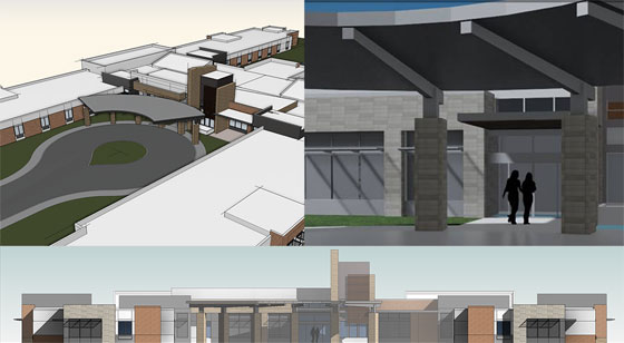
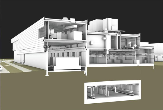
Image Courtesy: www.kssgroup.com

Ref: thenbs.com

~~~~~~~~~~~~~~~~~~~
Published By
Rajib Dey
~~~~~~~~~~~~~~~~~~~

Tuesday, December 30, 2014

Some handy BIM/VDC-associated technologies which can make a sea change in AEC Firms

The workflows of AEC firms are improved to a great extent with the implementation of building information modeling & virtual design and construction. Several upgraded techniques emerge out to transform 3d co-ordination process to a superior level.

The followings are some handy BIM/VDC-associated technology trends which facilitate the building team to design, build as well as operate buildings efficiently in the future course of time.

3D laser scanning: Lots of softwares contain less expensive field scanning techniques which perform through BIM models having perfect field information for construction sites. A scan is performed through the strong laser recording of the building structure that gathers the shape and look of a site. These conditions are transformed into a cloud of data points which are imported into a BIM model.

On a solo project, 30 minutes of scan time in the jobsite and 30 minutes of post-processing and uploading the point cloud into a Revit model can lead to saving of $30,000.

Model energy performance on the fly: With the emergence of new software tools, energy analysis of a building is executed throughout the conceptual design stage. Autodesk and Sefaira have launched various applications facilitating designers to accomplish energy study of early concepts on the fly. These applications compact the time required for assembling and crunching energy performance data for a long period. It facilitates the design teams to adapt their designs on the fly on the basis of the data.

Prefabrication will transform building delivery: Several Building Teams are applying BIM methods to collude with general contractors and construction managers to prefabricate and set up building components which range from mechanical equipment, plumbing infrastructure, and even complete restroom pods.

BIM makes the prefabrication process easy and smooth as the design become constructible in the model to be prefabricated and installed.

Data management: Some leading software companies like Assemble Systems and Panzura have built up cloud-based devices to manage, preserve, and distribute project data in a sophisticated way.

Computer-aided manufacturing: With the arrival of prefabrication and manufacturing processes like Lean construction, it opens savings and process efficiencies, the AEC are compelled to comply much the identical way computer-aided manufacturing changed manufacturing. Various CAM technologies together with BIM processes can deliver ready-to-install modules.

Some handy BIM/VDC-associated technologies which can make a sea change in AEC Firms
Image Courtesy: www.bdcnetwork.com

Ref.: http://www.bdcnetwork.com/

~~~~~~~~~~~~~~~~~~~
Published By
Rajib Dey
~~~~~~~~~~~~~~~~~~~

Thursday, December 25, 2014

How to find out the required time while completing a drawing in Autocad

Sometimes, it becomes necessary to know the time for completing a drawing in autocad (required by client for billing purpose) or evaluate your skill for completing the drawing with autocad in quickest possible time. All these are possible, if you use the ‘TIME’ command in autocad to find out the required time automatically while working on a drawing.

In order to apply the time command, provide time on the command section, the following records will be visible:-

  • Current time: It will display the present time along with the date

  • Created: The date and time for the creation of the drawing

  • Last updated: The time once the drawing was last saved

  • Total editing time: The accrued time incurred in drawing creation from session to session. AutoCAD does not take in plotting time or working time but quit devoid of saving your alterations

  • Elapsed timer: Also preserve time used in the drawing, but this can be activated or deactivated as well reorganized.

  • Next automatic save in: Notify you when your drawing will be saved automatically. You can set how frequently you save your drawing automatically. Just apply the OPTIONS command and display the Open and Save tab.

  • Next is the Enter option [Display/ON/OFF/Reset]: prompt. Following are the functionalities of these options:
    Display: Updates the listing by present times
    ON and OFF: Turns the elapsed time on and off
    Reset: Resets the elapsed time to zero

So these options are useful to help you in finding out the required time for completing a drawing.

Other option: The Express Tools EDITTIME command (type it on the command line) detects active editing time. It will function in a better way as compared to time command to represent your actual work perfectly. For start tracking, it should be activated. You can reset the time and apply the timeout option to postpone counting after a specific time of inactivity.

How to find out the required time while completing a drawing in Autocad

Image Courtesy: autocad-architecture-blog.com

Ref.: http://www.ellenfinkelstein.com

~~~~~~~~~~~~~~~~~~~
Published By
Rajib Dey
~~~~~~~~~~~~~~~~~~~

Thursday, December 18, 2014

Building Lifecycle Management (BLM) and its various advantages

Building Lifecycle Management (BLM) can be termed as a process for designing, assembling, and maneuvering a facility with a single set of interoperable data.

BLM employs a BIM Level 3 approach to allow a exceedingly developed Extended Collaboration process set up on the basis of Manufacturing industry best practices. BIM Level 3 will help in improving construction standardization, long-standing value for project owners as well as profit sharing for AEC project contributors.

BLM functions through a strong Product Lifecycle Management (PLM) system that produces a well-organized environment to organize complicated data associated with AEC (Architecture, Engineering & Construction) industry.

A BLM system is originated with the inclusion of BIM data to a PLM system.

BLM offers a wide array of significant advantages which range from better productivity, sustainability, and quality, as well as reduced waste, risk, and cost. BLM brings these advantages by disposing of rework, lessening RFIs (Requests For Information), consolidating data, contextualizing information and most of all forecasting outcomes perfectly.


As the data are consolidated centrally, it facilitates eliminating version control issues, possibilities for individual error, and even the requirement to handle files.

The users will be able to avail a single live database through web services and get rid of the issues like , rework (e.g., unnecessary drawings) and frequentness to a great extent.

With a BLM system, the users can solve any problem practically in advance. So occurrence of faulty RFIs, submittals, and change orders are minimized significantly.

Designers will be able to undertake more informed decisions inside a wealthy data context and keep up superior control over the quality of the finished product through BLM.

By working together under a BLM environment, the construction firms and building systems manufacturers can get the clear ideas on project requirements. By getting authentic data, builders and suppliers can make the coordination process better and understand the design intent efficiently.

BLM is formed to minimize waste by forecasting outcomes perfectly as well as detecting prospective clashes and optimizing practices. It will prevent expected cost overruns and standard risk margins.

By following the same system, BLM also minimizes risk to the project schedule, worker safety, and construction budget generally.

Manufactured systems like curtain walls and fac¸ades are considered as the most complex and expensive constituents of a construction project. The fac¸ade includes 15 percent of a construction budget. Generally Fac¸ade models do not involve data on the fabrication process, but manufacturing time can be trim down to a great extent (nearly up to 50 percent) if the fabrication process is identified in the design phase. A BLM system with transactable BIM data can make a strong collaboration amid the designer and the fac¸ade manufacturer.

While performing with building product manufacturers, the designers provide guarantee that the design intent is recognized and supply chain efficiency is enhanced, the whole project will be benefited.

BIM data from a series of systems are resolved inside the BLM environment, where issues are recognized and marked for further processing.

Building Lifecycle Management (BLM) and its various advantages

Image Courtesy : skybim.com


~~~~~~~~~~~~~~~~~~~
Published By
Rajib Dey
~~~~~~~~~~~~~~~~~~~