adsense analytic

Friday, January 29, 2016

Brief Overview of Model Based Definition (MBD)

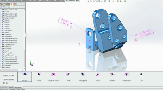
MBD represents model-based definition. MBD offers similar functionalities of PIM, or product information modeling. It offers unconventional way to dimension parts in both 2D and 3D.

It is the procedure of applying various 3D models like solid models, 3D PMI and related meta data inside any CAD software to offer specifications for specific components and product assemblies. There are various kinds of information in MBD which range from geometric dimensioning and tolerancing (GD&T), component level materials, assembly level bills of materials, engineering configurations, design intent, etc.

MBD facilitates to put both traditional and GD&T dimensions on the 3D model itself throughout the design phase. The engineer or designer can arrange these dimensions on the model for diversified applications.

Modern 3D CAD applications take into account the inclusion of engineering information like dimensions, GD&T, notes and other product details inside the 3D digital data set concerning components and assemblies. MBD applies such attributes to organize the 3D digital data set as the basis of these specifications and design authority for the product. The 3D digital data set may comprise of adequate information to manufacture and examine product devoid of any engineering drawings.

In several cases, applying some information out of 3D digital data set (e.g., the solid model) facilitates fast prototyping of product through different methods like 3D printing. A manufacturer can supply 3D digital data directly to manufacturing apparatuses like CNC machines to manufacture final product.

To learn more, go through the following exclusive article on MBD

Model Based Definition

~~~~~~~~~~~~~~~~~~~~~~
Published By
Rajib Dey
~~~~~~~~~~~~~~~~~~~~~~

Autodesk offers official support of Revit for Mac

Autodesk has announced an exciting offer for MAC users to access Revit through cloud. In this purpose Autodesk has tied a knot with Frame (https://fra.me/) to transform Revit to the cloud.

The is first ever official support of Revit toward Mac. Now the Revit users can easily reconfigure Revit into a virtual atmosphere that operates through authorized Autodesk applications via their computer’s browser.

The browser-run version lists support OS X, iOS, Android, Chromebook and Windows OS systems.

The browser version operates at fast paced out of the cloud and there is no need to use supplementary plug-ins. Therefore, the users can remain in Mac environments with out any difficulty for the complete experience.

In order to access this browser version of Revit at free of cost, visit cadonthecloud.com. Autodesk and Frame have also introduced some guides and FAQ sheets to solve your queries.


~~~~~~~~~~~~~~~~~~~~~
Published By
Rajib Dey
~~~~~~~~~~~~~~~~~~~~~

Thursday, January 28, 2016

How to use Revit Structure 2016 for slab detailing & arranging viewport

This Revit video is very useful for Revit users. By watching this video, one can learn how to use Revit Structure 2016 through Viewport Arrangement Process for Reinforcement Detailing of Slab. The detailing is made on Bottom Rebar & Extra Top Rebar.

If the Revit users require viewports and views, they don’t need to arrange viewports and views from the beginning each time rather they can save viewport arrangements with name as well as preserve them in case of requirement. Saved settings will involve the following :-


• The number and position of viewports

• The views that the viewports contain
• The grid and snap settings for each viewport
• The UCS icon display setting for each viewport


~~~~~~~~~~~~~~~~~~~~~~
Published By
Rajib Dey
~~~~~~~~~~~~~~~~~~~~~~

Tuesday, January 26, 2016

How to use isometric dimension and text in an isometric drawing

Go through the following CAD tutorial demonstrated by Jaiprakash, the leading CAD Corporate trainer and designer who currently associated with Ramboll.


The tutorial will teach you how to use AutoCAD based isometric dimension and text in an isometric drawing.

The isometric drawings are very useful for plant industry and with AutoCAD, it becomes easier to create the drawing. Isometric drawing does not refer to a 3D drawing but it is a 2D drawing created by modifying the orientation of drawing. It can be performed with the use of snap and afterwards modifying its style to isometric.

In the latest AutoCAD version, there is a ISODRAFT option. If AutoCAD 2015, the option is available in drafting settings, AutoCAD status bar. It will facilitate the users to instantly switch to isometric drafting mode.

Visit this link, to download isometric drawing https://goo.gl/NHZoXE


~~~~~~~~~~~~~~~~~~~~~
Published By
Rajib Dey
~~~~~~~~~~~~~~~~~~~~~

Monday, January 25, 2016

Ideate Explorer for Revit to optimize the works of MEP Engineers

Ideate Software, the leading developer of superior quality software, recently introduced Ideate Explorer for Revit. This newly launched software is specifically designed for Revit MEP users to optimize their workflow concerning Revit Building Information Model.


Revit professionals can apply Ideate Explorer to easily control Revit models as well as automate the process to locate, filter, measure, index, and choose a single and all elements in the existing view or whole Revit file.

Ideate Explorer for Revit offers the following functionalities :-

1. Discover, filter and modify elements, even those debarred from the project browse
2. Obtain a complete, detailed view of any Revit model and recognize all existing elements
3. Effortlessly sustain standards compliance and quality control with rapid project audits

Maintain your Revit projects error free, eliminate problem items to significantly minimize clumsy, inaccurate file size, and examine files instantly. Get and eliminate unappropriate, outdated and hidden problem items, together with DWGs. Smoothly choose all the Types inside a Family in short order. Get rid of choosing items in your Revit model manually.

Download a free trial ideatesoftware.com/download

Go through the online demonstration of this Revit add-in.


~~~~~~~~~~~~~~~~~~~~~
Published By
Rajib Dey
~~~~~~~~~~~~~~~~~~~~~

Thursday, January 21, 2016

Role of BIM for construction safety and risk management

Construction risks are considered as one of the most crucial factors for any construction jobsite. With the emergence of BIM, it becomes easier for construction professionals to generate 3D site safety plan as well as preserve safety plans electronically.


With BIM, the construction professionals can view and illustrate jobsite conditions for review and recognition of hazards. BIM can easily manage various issues like wrong work planning, deficient communication with workers and failure of safety training.

1. Visually examine jobsite conditions: BIM is used to get visual perception of a site briefly as well as the safety status all through the planning stage, prior to commencement of the actual construction. It facilitates the new workers to be familiar with the construction site safety measures and construction processes without difficulty.

2. Recognize possible hazards: As BIM offers 3D visualization, it becomes easier to generate 4D sequence and construction activity planning via site logistics. One can easily detect the possible hazards - specifically those distinctive to an individual project. So, with 4D scheduling feature, a characterized safety plan for workers is developed.

3. Exterminate risks and enhance safety conditions: By applying BIM, each risk can be highlighted independently and workflows can be organized efficiently which facilitate the each worker to optimize their tasks and get rid of possible risks.


BIM for construction safety and risk management
Image Courtesy: e-architect.co.uk
~~~~~~~~~~~~~~~~~~~~~~
Published By
Rajib Dey
~~~~~~~~~~~~~~~~~~~~~~

Trello for Revit – A useful add-in

Nathan Miller comes with a useful video for Revit users. This Revit tutorial will provide you the demonstration concerning an early functional prototype for a Trello Revit add-in.


This tool is used to deal with Trello-based boards, lists, and cards inside the Revit modeling surroundings.

Go through the online demonstration


Trello For Revit

~~~~~~~~~~~~~~~~~~~~~
Published By
Rajib Dey
www.bimoutsourcing.com
~~~~~~~~~~~~~~~~~~~~~

Tuesday, January 19, 2016

How to create family type catalogs in Revit

The youtuber RevitKid comes with a useful tutorial for Revit users. By going through this tutorial one can learn how to produce family type catalogs with Revit.


While generating large Revit families which consist of a number of types / variations (e.g. size) of the similar model, it is suggested to produce a ‘type catalog’ to go along with the family in your project. In brief, a type catalogue will decrease the amount of data to enter your model while importing a new component / family.

A type catalog records all of the types in a family, facilitating to select and load only the types required for the existing project that will minimize the file size of any project.

In order to make a type catalog, just generate an external text file (TXT) comprising the parameters and parameter values that make the diverse types in a particular family. Just assign this file in the similar location as the family file in order that while choosing to load the family, the type catalog is demonstrated.

The following points should be remembered :-

  • Generate type catalogs for families which have 6 or more types.
  • Parameter names are case sensitive.
  • For system parameters, the parameter inside the family should contain a value set earlier for the type to load the value out of the catalog perfectly.
  • In order to show inch marks in the type name, there should be 2 double quote symbols in the type catalog.


~~~~~~~~~~~~~~~~~~~~~
Published By
Rajib Dey
~~~~~~~~~~~~~~~~~~~~~

Monday, January 18, 2016

Fred Mills, Co-Founder of The B1M, speaks on 4D BIM

Fred Mills, Co-Founder of The B1M, briefly throws light on 4D BIM and how it impacts BIM projects through this exclusive youtube BIM video.

In simple terms, BIM is defined as the method of producing information models or data sets created with graphical and non-graphical information in a shared digital space called Common Data Environment (CDE). The information is developed in richness with the advancement of project phase till the whole data set is delivered to the Client and/or end user once the project is finished.

Once an information model is formed, scheduling data can be included to various components, providing perfect programme information and facilitating successive visuals concerning progression of project. This procedure is termed as 4D BIM.

Combining cost data with the purpose of supporting cost planning and creating estimates is identified as 5D BIM (http://www.theb1m.com/video/what-is-5...), whereas the addition of information to sustain facilities management and operation is titled 6D BIM (http://www.theb1m.com/video/what-is-6...).

4D BIM consists of time-related information that can be combined to several components concerning an information model. To deal with any particular element or work area, that could comprise details on its lead-time, construction and installation period, curing and drying allowances, sequencing or its interdependencies with other areas. With this detailed data, Planners will be able to instantly produce perfect programmes for projects, on the basis of one trustworthy source of federated information. The particular activities and items inside those programmes can be transparently associated with their graphical representations.

The addition of time-related attribute data also facilitates 3D visuals of a project’s growth being developed, demonstrating how it will be built up and how both the structure and surrounding site will be visible at all stages. By acquiring visual information instantly, the project team members can efficiently prototype assets in a virtual environment initially and offer quick feedback regarding modifications of design or methodology to their colleagues.

Thus the project delivery process will be accelerated as the approach will facilitate to disavow last minute on-site design co-ordination and revise as well as reduce waste from the delivery process in due course. The cost base for project teams and overall delivery cost for clients will be minimized significantly.

4D BIM is also a robust tool for exposure the influence of built assets with local Stakeholders throughout delivery and when completed. Each one will get clear idea and realize a apparent impression concerning how the asset will become visible, instead of having to visualize that from plans or Gantt charts.

4D can be applied at any phase of a project, and it can put in a lot of value and impact at the front end while evaluating the viability of schemes. It’s also functional all through tendering while comprehending a project within short span of time or illustrate and develop confidence around your technique as part of the selection process.


4D BIM

~~~~~~~~~~~~~~~~~~~~~~
Published By
Rajib Dey
www.bimoutsourcing.com
~~~~~~~~~~~~~~~~~~~~~~

Thursday, January 14, 2016

IMSI/Design LLC ships TurboCAD LTE Pro V8 to speed up 3D drafting, 3D detailing, 3D rendering and 3D visualization process

IMSI/Design LLC launched the most updated version of its flagship product TurboCAD LTE Professional alias TurboCAD LTE Pro V8. This latest CAD program contains some advanced features which can speed up and improve drafting, detailing, rendering and visualization process. These features range from a new Conceptual Selector, superior file sharing with AutoCAD and SketchUp, better BIM (building information modeling) support and new tools for its architectural users.

V8 is compatible with Windows 10 and offers upgrdings to its productivity, usability and interoperability features.

TurboCAD LTE Pro has the similar functionality of AutoCAD LT. It applies the same UI (user interface) and command line, and it facilitates opening and saving DWG, DXF and DWF formats. Version 8 introduces DWG/DXF read/write filters for AutoCAD 2013-2015 and dynamic blocks can import as simple blocks. TurboCAD LTE Pro can also be used to import/export of SketchUp 2015 files.

TurboCAD LTE Pro V8 contains a new Conceptual Selector for controlling and revising 3D objects.

This feature can be applied to customize any visual and editing parameters like move, scale or rotate accessible in TurboCAD LTE Pro. The users get the ability to generate and manage contact lists as well as transmit files to individuals or groups from inside TurboCAD LTE Pro with new Contact Manager and File Sharing capabilities.

V8 comes with a new default option that automates the process for saving any custom-made documents users have opened while closing the application. The document then reloads while opening TurboCAD LTE Pro next time. Other productivity and usability features contain a new option to save the Undo/Redo buffer while closing a file. The buffer reloads while opening the file again.

TurboCAD LTE Pro’s Drafting Palette supports solid or surface models, converting 3D designs into correlative 2D views and detailed sections with a single click, even while dealing with an Xref.

Download a trial version TurboCAD LTE Pro v8 Trial

TurboCAD LTE Pro v8 Trial

~~~~~~~~~~~~~~~~~~~~~
Published By
Rajib Dey
~~~~~~~~~~~~~~~~~~~~~

How to use revit for creating drawing in the foreground

The youtuber Daniel Severino has presented this exclusive revit tutorial that teaches you how to set the perceptibility of components in floor paging environment devoid of the hatch overlaps the object in the assigned project with Autodesk Revit.

Download Revit 2016 | Free Trial www.autodesk.com/products/revit-family.


How to use revit for creating drawing in the foreground

~~~~~~~~~~~~~~~~~~~~~~
Published By
Rajib Dey
~~~~~~~~~~~~~~~~~~~~~~

Wednesday, January 13, 2016

IMAGINiT introduced Scan to BIM 2016.1 with some advanced features

BIM offers some advanced technology like large-scale 3D scanning of a building, an entire city as well as complicated architectural details. Once the scan is delivered to BIM software, if often requires to retreat the shapes manually for modeling purpose. The process is very laborious and tedious.

Point clouds are included in 3D laser scanning system. This technology is ideal for scanning large areas efficiently and in quickest possible time. But in order to convert them into accessible information, specialized software is essential.

Scan to BIM for Revit is such kind of software that generates native Revit geometry out of a point cloud to identify and assign several architectural elements like walls and columns to pipes and ductwork.

IMAGINiT develops Scan to BIM and the latest version is Scan to BIM 2016.1. This new version contains some advanced features which are described below :-

The first new feature is known as Create Mesh that facilitates the users to model complicated details like elaborate steeples as well as gargoyles smoothly. Besides, the users can also produce custom families and native Revit geometry out of these details.

Go through the following video for its functionalities :-

Create Mesh can streamline the process for remodeling, renovation and even historic preservation projects.

The another exciting feature is Auto-Find Walls that facilitates the users to explore with millions of points, lots of which symbolize single walls. With parameters like least height and width, it can generate a set of discovered walls and transform them into Revit elements. It also make differentiation amid other surfaces like floors and ceilings.

Go through the following video to get a live demonstration :- The users can avail a 21-day trial version that supports Revit 2014, 2015 or 2016.

To get more updates, visit IMAGINiT Scan to BIM website (www.imaginit.com)

Put Point Clouds to Work in Revit with Scan to BIM

~~~~~~~~~~~~~~~~~~~~~~
Published By
Rajib Dey
~~~~~~~~~~~~~~~~~~~~~~

Thursday, January 7, 2016

How BIM is considered as a useful tool for landscape architects

This exclusive BIM video tutorial is presented by youtuber BIMEquity where it is briefly explained how BIM brings huge benefits to Landscape architects by generating 3d views of complicated shapes.


By watching this video one can learn how to generate a terrain profile involving a road, a path, a wall and add water in 3D.


~~~~~~~~~~~~~~~~~~~~~~
Published By
Rajib Dey
www.bimoutsourcing.com
~~~~~~~~~~~~~~~~~~~~~~

Tuesday, January 5, 2016

How does V-ray for Revit work?

This youtube video sheds light on the functionalities of the V-ray for Revit. Now design professionals will be able to apply V-Ray core rendering technology in their design progression as V-ray is now incorporated with Revit.

There are some exciting toolset for VR output, materials and environments. Take advantages of Revit cameras, lighting, and materials. There also exist an integrated visualization pipeline having compatibility with all V-Ray design packages (SketchUp, Rhino, and 3ds Max).


~~~~~~~~~~~~~~~~~~~~~
Published By
Rajib Dey
~~~~~~~~~~~~~~~~~~~~~