adsense analytic

Showing posts with label AutoCAD Blocks. Show all posts

Monday, July 23, 2018

Mastering AutoCAD 2018 and AutoCAD LT 2018 – An exclusive e-book for CAD professionals

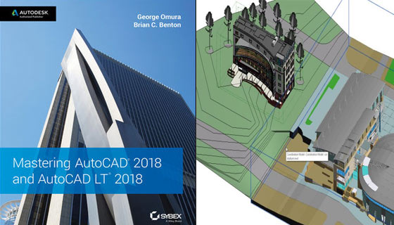
George Omura, a licensed architect and Autodesk Authorized Author and Brian C. Benton, senior engineering design technician have written an exclusive ebook titled as “Mastering AutoCAD 2018 and AutoCAD LT 2018 for CAD professionals.

If you’re new to AutoCAD, this book will be your “bible;” if you’re an experienced user, this book will introduce you to unfamiliar tools and techniques, and show you tips and tricks that streamline your workflow.

Mastering AutoCAD 2018 and AutoCAD LT 2018 is specifically designed for the design and drafting professional to fulfill their requirements. With Step-by-step guidelines, the book sheds light on the latest AutoCAD tools and techniques.

The book contains hands-on projects to improve your practical skills which can be employed directly to real-world projects. The companion website highlights the related project files and other bonus content to facilitate the users to deal with each important technique. This new edition is updated to contain the latest AutoCAD and AutoCAD LT features so that the users can deal with real-world projects efficiently.

Major Features

The book contains the following exclusive features :-

• Improve your skills with the elementary drafting tools which should be applied in every project
• Learn how to deal with hatches, fields, tables, attributes, dynamic blocks, and other intermediate tools
• Transform your 2D drawing into a 3D model with advanced modeling and imaging methods
• Customize AutoCAD to adapt the way you work, combine outside data, and much more.


To purchase the book online, click on the following link. (For outside India) / (For India)

Mastering AutoCAD 2018 and AutoCAD LT 2018 – An exclusive e-book for CAD professionals


~~~~~~~~~~~~~~~~~~~~~~~~
Published By
Rajib Dey
www.bimoutsourcing.com
~~~~~~~~~~~~~~~~~~~~~~~~

Saturday, July 7, 2018

nanoCAD 5.0 – The newest powerful CAD software

Nanosoft launched nanoCAD 5.0. It is a free, fully operative CAD software. After making registration and activating the software, the users can obtain a one-year renewable license and utilize the software for any purpose.

Once the software is installed, the users will be able to import drawing (DWG) files or develop new projects as well as export and share with others, devoid of any watermarks.

Top Three New Features of nanoCAD 5.0

nanoCAD provides support for DirectX graphics and it is now the standard for graphics performance for Microsoft Windows. DirectX is mostly recognized for gaming, but its graphics performance functions efficiently with computers and lower-end graphics cards. In nanoCAD 5.0, you can select which graphic library, OpenGL or DirectX, is considered as the perfect option for your video card. It can be accessed by opening the Options dialog box and selecting Graphic settings. (Image courtesy of Nanosoft.)

It is compatible with AutoCAD 2013/2014 version DWG files. nanoCAD can now read and write AutoCAD-supported DWG files which are well-suited with DWG files compatible with AutoCAD 2013.

Better object selection - The Quick Selection (QS) command is upgraded significantly and extended with a few vital capabilities. Now the users will be able to produce selection conditions for graphic primitives like arcs, polylines, splines and lines. The QS command in nanoCAD 5.0 also facilitates the users to produce selection conditions for complicated objects like tables, notes, dimensions and blocks.

The users can now add a block with .dxf file extension for greater adaptability.

nanoCAD products comprise of nanoCAD Plus, nanoCAD Pro, nanoCAD Mechanica, nanoCAD Construction, nanoCAD Construction Site.

To download nanoCAD 5.0, go through the following link nanocad.com

nanoCAD 5.0 – The newest powerful CAD software

~~~~~~~~~~~~~~~~~~~~~~~~
Published By
Rajib Dey
www.bimoutsourcing.com
~~~~~~~~~~~~~~~~~~~~~~~~

Wednesday, July 4, 2018

Details of AutoCAD coordinates

There are 3 types of AutoCAD coordinates system which are given below :-

ABSOLUTE COORDINATES
RELAVIE COORDINATES
POLAR COORDINATES

All input points are mentioned in your drawing with standard Cartesian coordinates x and y.
ABSOLUTE COORDINATES
With the use of absolute coordinate, points are inputted by typing x, y (Enter).
RELATIVE COORDINATES
As soon as the first point is inputted, your next points will be inputted by indicating the next coordinate compare/relative from the first points. The relative coordinate is commenced with the symbol “@” to inform AutoCAD that it is a relative coordinate. With relative coordinate, the points are inputted by typing @x,y (Enter).
POLAR COORDINATES: Polar coordinates are applied when it is required to draw the next points at specify angle. Polar coordinates system in AutoCAD indicates distance length at which angle. With polar coordinate, points are inputted by typing @distance < angle (Enter).
Details of AutoCAD coordinates

~~~~~~~~~~~~~~~~~~~~~~~~
Published By
Rajib Dey
www.bimoutsourcing.com
~~~~~~~~~~~~~~~~~~~~~~~~

Monday, July 2, 2018

Improve your AutoCAD skills with a series of 30+ AutoCAD 2D and 3D drawings

Jaiprakash Pandey, the renowned mechanical engineer and Autodesk AutoCAD Certified Professional, has conducted an online course for AutoCAD users. The users can enhance their AutoCAD skills with a series of 30+ AutoCAD 2D and 3D drawings.

This course is specifically designed for the users who possess minimum knowledge of AutoCAD 2D and 3D tools as well as for those users who have already finished AutoCAD 2D or 3D courses on SourceCAD.

The course comprises of numerous 2D and 3D drawings which can be used for operating the tools learned throughout the AutoCAD course. There are three main sections which include AutoCAD 2D, 3D and advance 3D drawings of objects from real life like Nut, bolt and gears.

Course Topics:
• 2D and 3D practice drawings
• Downloadable PDF and DWG file with dimensioning
• Frequently updated content
• Advance 3D projects like coupling and Coke bottle included

Pre-requisites:

• Minimum knowledge of AutoCAD 2D and 3D tools
• AutoCAD 2013 or any later version
To register online, go through the following link learn.thesourcecad.com

Improve your AutoCAD skills with a series of 30+ AutoCAD 2D and 3D drawings

~~~~~~~~~~~~~~~~~~~~~~~~
Published By
Rajib Dey
www.bimoutsourcing.com
~~~~~~~~~~~~~~~~~~~~~~~~

Tuesday, June 26, 2018

Steps associated with MEP Coordination Systems

MEP coordination is considered as one of the most vital process in construction that should be given special attention. The system makes sure that the structural framework and architectural design are not conflicted with its MEP-FP systems. Based on the level of details (LOD) and need of the client, the MEP coordination method differs in every organization. MEP Coordination Systems contains the following stages :-

1. Assessment of Consultant Design Drawings and Structural/Architectural Plans: Preliminary, the MEP coordination service facilitates the organization to obtain single line drawings from the MEP-contractors or consultants. Afterward, they study the structural and architectural plans thoroughly. Besides, they study the MEP specifications except for the assessment of drawings, layouts with reliability. Finally, MEP coordination services provider designs a brief plan for coordination.

2. 3D Prototype Formation: To fulfill the need in initial phase, the MEP coordinator generates an accurate 3D model by applying AutoCAD or Revit. This 3D model demonstrates total MEP services with adherence to the architectural and structural conditions of the building. Besides, this entire model acts as the base for various other important development-related plans, elevations or sections. MEP coordinator employs the 3D model for client inputs as well as generating complete walkthroughs.

3. Conflict detection and Resolution: In this phase, the 3D model set up earlier is tested for clashes among the MEP systems and the design elements. For this, they use Navisworks, a particular clash-detection software application. It detects all types of clashes like workflow clashes, geometry-related hard clashes, and clearance clashes. Besides, the MEP coordinator detects possible alternatives and deliver them to the clients.

4. Formation of Coordinated Sections and Drawings: Once a 3D model is tested for vertical and horizontal coordination, then the drawing sets are arranged to demonstrate how MEP-FP systems function in coordination as well as for more transparency, annotation and tagging process. The organizations who are liable to control MEP coordination can get elevation, section, and isometric views from the 3D model produced earlier. Besides, these can be applied for client explanations.

5. Formation of Detailed Service Drawings: In this stage, all the structural service-by-service drawings are generated and the details are included with reference to their dimensions like heights, and distances from gridlines. Site installation teams utilize these drawings and develop the base for fabrication drawings.

6. Formation of Spool, Fabrication Drawings, and Hangar Drawings: On basis of the scope of work, particular services drawings are utilized to generate fabrication drawings through some software or detailing. These drawings illustrate fabrication features for ductwork, and hence the CNC machines can directly identify them for rendering purposes.

If required, the MEP coordination unit also indicates the details of the model to create spooling data for production crews. Except for this, the firm can even plan out and then demonstrate the hangars for every design. As soon as the plan is made, the hangar specifications are provided on a list for the production units.

In MEP coordination systems, some steps may be omitted with regards to the scope of the project. Although each point is important for completing any project successfully devoid of any setbacks, additional cost, and unanticipated design amendments.

7. As-Fitted Modifications: This final step is associated with making modifications to the design model and the pictures because of some site changes from the construction designs. If the coordination work is perfect, and the installation is done according to the construction drawing directions and plans, the amendments to the as-fitted (also defined as as-installed and as-built) designs are least amount.

Source: blog.nibt.education

Steps associated with MEP Coordination Systems

~~~~~~~~~~~~~~~~~~~~~~~~
Published By
Rajib Dey
www.bimoutsourcing.com
~~~~~~~~~~~~~~~~~~~~~~~~

Thursday, June 14, 2018

Some useful AutoCAD commands to improve your CAD modeling skills

1) CHAMFER:- It is used to produce bevel about a corner.
Activation:- 
Alter Toolbar => Chamfer icon.
Alter menu => Chamfer option.
Type CHAMFER or CHA at “COMMAND:” prompt and press enter

2) PLOT :- It is applied to print the drawing on paper.
Activation:- 
Ctrl+P is the shortcut key
File menu => Plot option.
At “COMMAND:” prompt, type PLOT and press enter

3) LENGTHEN:- It is helpful for modifying the length of an accessible line. It is also possible to view the length of a selected line at command prompt.
Activation:- 
Alter toolbar => Lengthen option.
At “COMMAND:” prompt, type LENGTHEN or LEN and press enter
4) XLINE (Construction Line) :- It is a useful command to generate a endless line.
Activation:- 
Draw toolbar => Construction Line icon.
Draw menu => Construction Line option.
Type XLINE or XL and press enter at “COMMAND:” prompt.

5) ATTDEF (Attribute Definition) :- It is applied to include block attribute to a block. An attribute stands for a label or tag that connects data to a block.
Activation:- 
Draw menu => Block option => Describe Attribute option.

Type ATTDEF or ATT and press enter at “COMMAND:” prompt.

6) INSERT :- It is suitable for inserting an accessible Block in the active file.
Activation:- 
Draw toolbar => Insert Block icon.
Insert menu => Block option.

Type INSERT or I and press enter at “COMMAND:” prompt.
7) WRITE BLOCK :- It is utilized to generate a New Block. When Write Block command is applied to produce Block, the resultant block is applicable in any AutoCAD File.
Activation:- 
Type WBLOCK and press enter at “COMMAND:” prompt.
8) BLOCK :- It is applied to make a New Block. When Block command is used to produce the block, the resultant block is employed in the source file only.
Activation:-
Type BLOCK and press enter at “COMMAND:” prompt.
9) DIVIDE :- This command is applied to Divide an object into several identical divisions.

Activation:- 
Draw menu => Point option Divide option.

Type DIVIDE or DIV and press enter at “COMMAND:” prompt.
10) MEASURE :- This command is utilized to break up an object into some divisions of defined equivalent length.
Activation:-
Draw menu => Point option Measure option.
Type MEASURE or ME and press enter at “COMMAND:” prompt.
To get more commands, go through the following link mycivil.engineer

Some useful AutoCAD commands to improve your CAD modeling skills

~~~~~~~~~~~~~~~~~~~~~~~~
Published By
Rajib Dey
www.bimoutsourcing.com
~~~~~~~~~~~~~~~~~~~~~~~~

Thursday, January 18, 2018

progeSOFT SA released progeCAD’s iCADMac 2018 for Mac

Swiss-based progeSOFT SA released iCADMac 2018, a complete and professional 2D/3D DWG-based CAD system that has the ability to read and write AutoCAD files up to version 2018.

This newest version is compatible with Apple’s macOS El Capitan and High Sierra operating systems. The user interface is significantly improved to simplify the working process.

By applying more complete, contextual menus system, time & the numbers of mouse clicks can be saved significantly.

In iCADMac 2018, there are two user interfaces available for the users. The users can choose from either the classic “light grey” theme or the new “dark 2018” theme. With the help of the vector-based icons in the macOS menu architecture, high-resolution 4K displays are possible on Apple’s computers.

There are various new tools contained in iCADMac 2018 which range from a new AutoComplete feature to accelerate typing commands and system variables. SuperHatch generates an area hatch with an image, a block, an external reference, or a wipeout.

There exist new features for managing hatches and gradients. Trimmed hatches stay associative and function as a single entity. With a revamped dialog box, enhancements are also made to print dialogs. New Auto-Hide palettes are used to break down palettes automatically while shifting the pointer away from the palette. Palettes are expanded automatically while moving your pointer back towards them.

To get more information, click here: www.progesoft.com

progeSOFT SA released progeCAD’s iCADMac 2018 for Mac

~~~~~~~~~~~~~~~~~~~~~~~~
Published By
Rajib Dey
www.bimoutsourcing.com
~~~~~~~~~~~~~~~~~~~~~~~~

Wednesday, January 10, 2018

Improve your AutoCAD skills with a series of 30+ AutoCAD 2D and 3D drawings

Jaiprakash Pandey, the renowned mechanical engineer and Autodesk AutoCAD Certified Professional, has conducted an online course for AutoCAD users. The users can enhance their AutoCAD skills with a series of 30+ AutoCAD 2D and 3D drawings.

This course is specifically designed for the users who possess minimum knowledge of AutoCAD 2D and 3D tools as well as for those users who have already finished AutoCAD 2D or 3D courses on SourceCAD.

The course comprises of numerous 2D and 3D drawings which can be used for operating the tools learned throughout the AutoCAD course. There are three main sections which include AutoCAD 2D, 3D and advance 3D drawings of objects from real life like Nut, bolt and gears.


Course Topics:
• 2D and 3D practice drawings
• Downloadable PDF and DWG file with dimensioning
• Frequently updated content
• Advance 3D projects like coupling and Coke bottle included
Pre-requisites:
• Minimum knowledge of AutoCAD 2D and 3D tools
• AutoCAD 2013 or any later version
To register online, go through the following link learn.thesourcecad.com
Improve your AutoCAD skills with a series of 30+ AutoCAD 2D and 3D drawings

~~~~~~~~~~~~~~~~~~~~~~~~
Published By
Rajib Dey
www.bimoutsourcing.com
~~~~~~~~~~~~~~~~~~~~~~~~

Tuesday, October 24, 2017

How to use AutoCAD 2018 for practicing 3d drawing

In this AutoCAD video tutorial, you will learn how to perform 3D practice drawing in AutoCAD 2018.


AutoCAD 2018 simplifies the 2D drafting, drawing and annotation as follow :-
• Text settings: Generate single or multi-line text (mtext) as a single text object as well as format the text, columns and boundaries.
• Smart dimensioning: Automate the process for making dimensions. Move the cursor over chosen objects to have a glimpse prior to form it.
• Leaders: Produce leaders with diversified content, along with text or blocks. Format leader lines and define styles with some easy to follow process.
• Smart centrelines and centre marks: Generate and edit centrelines and centre marks to be progressed automatically if you shift the related objects.
• Tables: Make tables containing data and symbols in rows and columns, employ formulas and link to a Microsoft Excel spreadsheet.
• Revision clouds: Draw revision clouds around new changes in a drawing to make out your updates instantly.
• Layouts: Indicate the size of your drawing sheet, include a title block and demonstrate multiple views of your model.
• Layout viewports: Generate layout viewports to present various components of your design at changeable scales.
• Fields: Apply fields in text objects to demonstrate text that will be updated automatically when the field value modifies.
• Data linking: Facilitate concurring updates with formation of a live link among a Microsoft Excel spreadsheet and a table in your drawing.
• Data extraction: Extract information from objects, blocks and attributes, along with drawing information.
• Parametric constraints: Use geometric and dimensional constraints to retain relationships among drawing geometry.
• Express tools: Extend the power of AutoCAD with a collection of productivity tools.
Learn more (knowledge.autodesk.com)


Read more

~~~~~~~~~~~~~~~~~~~~~~~~
Published By
Rajib Dey
www.bimoutsourcing.com

~~~~~~~~~~~~~~~~~~~~~~~~


Wednesday, August 2, 2017

How to create command aliases for full length command in AutoCAD 2000

Join Lynn has presented an exclusive video tutorial where he briefly explains the simple method to create Command aliases, shortened versions of the full-length commands.

By customizing the commands you can work according to your choices. These commands are compatible with AutoCAD 2000.

Command Alias Editor. In command alias, create a new command alias. Suppose, you want to change copy command and change it to BB. You have to ensure that there is no command in AutoCAD or Normal AutoCAD for BB. Now, if you put BB command in command section and press enter, it will activate the copy command as same.à Tools -àTo do this, you have to go to Express Tools –


To get more command aliases, watch the following video.


Read more

~~~~~~~~~~~~~~~~~~~~~~~~
Published By
Rajib Dey
www.bimoutsourcing.com

~~~~~~~~~~~~~~~~~~~~~~~~

Saturday, July 29, 2017

How to use TrussCAD, a autocad based program, to draw roof truss section detail

In this autocad tutorial, you will learn how to create the drawing of a roof truss section detail with the use of AutoCAD. You will also learn how section detail can be produced with lines, polylines, and hatches.

The tutorial is created with TrussCAD, an exclusive plugin program for AutoCAD.

It can be used to sketch timber roof and floor trusses in your AutoCAD drawings together with roof battens and roof tiles rapidly and save significant time.
The created lines can be entirely edited in AutoCAD if necessary. Trusses are formed on the basis of the user input and can be edited like standard AutoCAD lines and polylines. All colors of the line work can be modified to fit your office standards. With TrussCAD, it is possible to arrange roof battens on the Roof trusses for both Tiled and Sheet roofs.

The roof battens for tiled roofs also produce the roof tiles.

It supports full versions of AutoCAD 2000 and higher.

To download the software, click on the following link thirdistudio.com.au/TrussCAD
The files which are used in this tutorial can be downloaded from the following linkwww.thirdistudio.com.au


To get more details, watch the following video.


Read more

~~~~~~~~~~~~~~~~~~~~~~~~
Published By
Rajib Dey
www.bimoutsourcing.com

~~~~~~~~~~~~~~~~~~~~~~~~

Tuesday, July 25, 2017

Functionality of annotative dimensions lines in AutoCAD

This is an exclusive autocad tutorial video that teaches you how to add annotative dimension lines in an autocad drawing.

The annotative dimension lines are ideal while going to print a drawing with viewports in various scales.

Fundamentally, the sizes to be edited in the dimension style manager, is same as that will be provided in the paper while printing.

With dimension style manager, it is possible to generate new styles, arrange the existing style, rectify styles, set overrides on the existing style, and compares styles.

A dimension style belongs to a named collection of dimension settings that manages the look of dimensions like arrowhead style, text location, and lateral tolerances.

The objective of dimension styles is to indicate the format of dimensions instantly, and to make sure that dimensions comply with industry or project standards.

The video focuses on the following topics :-
-Edit annotative dimensions
-Produce a special layer for dimension lines (command DIMLAYER)
-Draw annotative dimension lines -scale 1:100 -scale 1:30
-Display and hide annotation objects


To get more details, watch the following video.

Read more

~~~~~~~~~~~~~~~~~~~~~~~~
Published By
Rajib Dey
www.bimoutsourcing.com

~~~~~~~~~~~~~~~~~~~~~~~~

Saturday, June 17, 2017

An exclusive autocad course on 2D and 3D Elevations

Take part in an exclusive AutoCAD course that involves 2D and 3D Elevations. This course will help you to enhance your designing skills for generating professional 2D and 3D elevations.

This course will provide brief guidelines on how to apply AutoCAD to organize perfect plans, as well as rectify layouts, fine-tune viewports, insert 2D elevations, and develop 3D elevations.

Join Shaun Bryant will perform as course instructor and he will train you how to customize layers, hatches, backgrounds, annotations, modelspaces, and more.
The course of will sift through the following topics :-
• Designing elevations
• Organize plans and construction lines
• Isolating elevations
• Arrangement of elevation layers
• Dealing with hatches
• Using background colors
• Inserting annotations
• Organize dimension layers and styles
• Placing an elevation in a viewport
• Freezing viewport layers
• Setting up modelspace viewports
• Setting the viewport scale
• Publishing multiple elevation layouts

To get more information about the course, click on the following link AutoCAD: 2D & 3D Elevations
An exclusive autocad course on 2D and 3D Elevations
Read more
~~~~~~~~~~~~~~~~~~~~~~~~
Published By
Rajib Dey
www.bimoutsourcing.com
~~~~~~~~~~~~~~~~~~~~~~~~

Tuesday, May 30, 2017

New Updates For AutoCAD 2017 For Mac And AutoCAD LT 2017 For Mac From Autodesk

Autodesk has made a significant update to the AutoCAD for Mac product line, which comprise AutoCAD 2017 for Mac and AutoCAD LT 2017 for Mac.
New Touch Bar Support: Touch Bar support for the latest and popular MacBook Pro laptops is included in version AutoCAD 2017.1.
There are three major updates in AutoCAD version 2017.1 which contain the Touch Bar support, user interface improvements and migrating settings functionality.
With Touch Bar support options, the users can get access to turn on and off items like the grid, snaps, object snap tracking, as well as the command line window. It is a very light-handed approach.
The new Autodesk support for the MacBook Pro’s new Touch Bar comprises of default support for 10 functions which can be pulled as a set to the Touch Bar interface. The users will be able to modify this arrangement by inserting from a list of approximately half a dozen other controls to substitute in. There are various features like ISO plane, Object Snap Tracking, Grid On/Off, Dynamic UCS, Snap Mode, and Command Window for adjusting the Touch Bar while operating AutoCAD 2017.1 for Mac or the LT version on a MacBook Pro.
There are other significant UX/UI features like the new abilities to dock and undock the Layers palette and the Properties inspector. This will provide huge benefits to the users who are applying AutoCAD for Mac on two monitors and apply them in a way where the drawing window is arranged on one screen and the palettes on another.
Another significant feature is the improvement to the settings dialog. Now the Users will be able to pass their custom settings to future updates and no longer lose these upon doing so.
With great customization skills, the users get the ability to include or eliminate items from both standard pull down menus and the Tool Sets Palette.
To learn more about Autodesk AutoCAD 2017 for Mac and AutoCAD LT 2017 for Mac and the updates available visit here. For information on the AutoCAD for Mac product line visit here.

To get more information, click on the following link architosh.com

New updates for AutoCAD 2017 for Mac and AutoCAD LT 2017 for Mac from Autodesk


~~~~~~~~~~~~~~~~~~~~~~~~
Published By
Rajib Dey
www.bimoutsourcing.com
~~~~~~~~~~~~~~~~~~~~~~~~

Thursday, May 4, 2017

Demo Of Design View Enhancements In AutoCAD 2018

This AutoCAD tutorial video demonstrates the design view enhancements feature in AutoCAD 2018.
Share Design Views function has been restructured in AutoCAD 2018 to provide support to the new DWG file format, and the A360 viewer provides more adaptability as compared to previous versions.
The AutoCAD users can now simply publish views of drawings to the cloud to allow collaboration among stakeholders and at the same time safeguard your DWG files.
The design view tool can be availed from the publish fly out on the application menu or from the A360 ribbon tab by applying the ONLINEDESIGNSHARE command.
The design views are located online through a link that can be allotted with collaborators. Now, It is possible to get your recent uploads from the A360 viewer home page.

By default, uploads are only available for 30 days. But the new version facilitates the users to spread a design view for an extra 30 days at any time, along with an unrestrained number of extensions.


Besides, allocating your design views, it is now possible to post, review, and resolve comments.


Read continue

~~~~~~~~~~~~~~~~~~~~~~~~
Published By
Rajib Dey
www.bimoutsourcing.com

~~~~~~~~~~~~~~~~~~~~~~~~