adsense analytic

Showing posts with label 3D CAD. Show all posts

Friday, April 21, 2017

How To Perform Hatching In AutoCAD For Designing A Kitchen In 3D

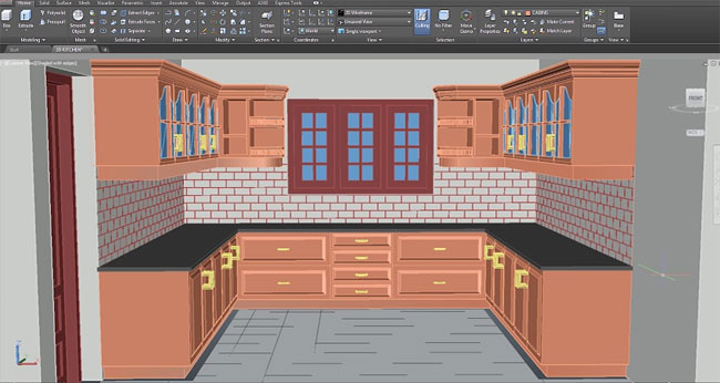
This video tutorial teaches you the procedure to perform hatching in 3D, by creating the tile effect on the walls , floor on the 3D kitchen tutorial.
This CAD video shows the detailed processes for creating a 3D model of kitchen with tile effect on the walls, floor. The video is specifically designed to teach you how to create hatching in 3D. You will be able to various kitchen elements like cabinets, handles, doors, windows etc. 3D.
AutoCAD users and drafters generally apply hatching to demonstrate the type of material that is used to form an object, like insulation, metal, or concrete. Alternatively, hatching facilitates highlight or simplify the extent of a specific component in the drawing.

To carry out a hatching in AutoCAD on a desired plane in 3D dimension, it is necessary to coordinate the user coordinate system or UCS on that specific plane. In this context, the most preferred method will be applying face option of UCS command. Just click on the visualize tab and select face option from drop down menu and click on the chosen plane.

Now, X, Y will be aligned on that plane. Press enter to accept it.
The hatching is performed with the following two methods :-
Ray Casting Method – Here, select a point on the chosen area where a specific pattern will be filled.
Boundary Method – Indicate the boundaries where the pattern should be filled.


For more information, watch the video.

How to perform hatching in AutoCAD for designing a kitchen in 3D


~~~~~~~~~~~~~~~~~~~~~~~~
Published By
Rajib Dey
www.bimoutsourcing.com
~~~~~~~~~~~~~~~~~~~~~~~~

Friday, March 24, 2017

AutoCAD 2016 Tutorial On Cameras, Materials, Lighting And Rendering

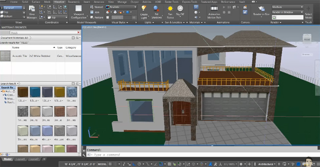
Learn the detailed process for creating a 2d house plan as well as 3d model of the house with the use of AutoCAD by going through this AutoCAD video tutorial.


The video sheds light on the following topics :-
Generating Cameras
Using Materials
Lighting
final Preview of the project
In this tutorial, AutoCAD 2016 is used.


AutoCAD 2016 Tutorial on cameras, materials, lighting and rendering

~~~~~~~~~~~~~~~~~~~~~
Published By
Rajib Dey
www.bimoutsourcing.com
~~~~~~~~~~~~~~~~~~~~~~

Thursday, June 16, 2016

FixtureBuilder – The newest 3d modeling program for CAD professionals

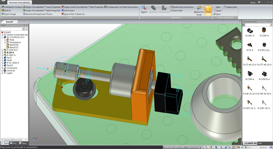
Renishaw introduced FixtureBuilder for 3d modeling professionals. It is a 3d modeling package to facilitate the formation and documentation of fixturing set-ups.

The software is applied with a CAD model of the examined part that can be imported into FixtureBuilder, so as to the fixture is developed around it. The complete set-up, together with the examined part, will be exported into inspection programming software.

FixtureBuilder is capable of importing and exporting most common 3D CAD files (Parasolid, Step, ACIS, STL, IGES, etc.). There is a supplementary translator module for CATIA, ProE, UGNX, Solidworks and Inventor accessible for purchase.

With it, the users will be able to generate custom fixturing set-ups and components, like custom plates, and preserve them in user-defined libraries for being used later on and reference.

There is a ‘Build it' function in the software that can automatically generate a comprehensive Bill of Materials and work instructions for each fixture set-up, and allows to adhere to ISO, QS9000 and other quality standards.

Other crucial features are Primary benefits include clear, methodical component libraries; smart “drag and drop” functionality; instant management of parts; and a simplified constraint mechanism.

For more information, visit www.renishaw.com


FixtureBuilder – The newest 3d modeling program for CAD professionals
Image Courtesy: renishaw.com

~~~~~~~~~~~~~~~~~~~~~
Published By
Rajib Dey
~~~~~~~~~~~~~~~~~~~~~

Monday, March 21, 2016

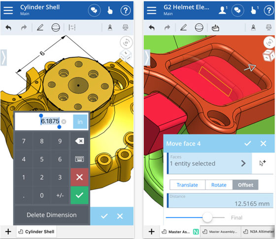
Now Onshape includes new features for iPad Pro & Apple Pencil to transform your 3D Cad modeling process to the next level

Onshape, the leading solution provider in cloud and mobile CAD, introduces its first ever iOS app compatible with iPad Pro and Apple Pencil.

With the inclusion of new "Force Zoom" feature, the users will be able to segregate a single pixel through the pressure-sensitive Apple Pencil. If the CAD users need to choose a specific piece of 3D geometry, they can take help from pressure to Pencil to zoom in and expand smaller portions. The tighter they press the screen, the zoom will be narrower. If you discharge the pressure, the screen will be returned to its original view.

Apple Pencil offers a two-handed workflow. The users can easily revolve or pan a model with single hand as well as apply Pencil to sketch, select and interrelate with the 3D models.

iPad Pro is enriched with superior portability, robust graphics, and CAD-friendly screen. iPad Pro provides multitasking capabilities like Split View, Picture in Picture, and Slide Over with which it becomes easier to switch back and forth amid apps or websites.

By applying Split View, a product development engineer can easily search for specifications out of a supplier catalog and simultaneously function on a model.

If the CAD users want to learn how to design on their iPad or iPhone, they can visit the Apple App Store and Onshape.com/Learn. To create a free account, sign up in the app or visit Onshape.com/signup.

The CAD users can access Onshape for iPhone & iPad App at free of cost in the Apple App Store.

3D Cad modeling
Image Courtesy: itunes.apple.com

~~~~~~~~~~~~~~~~~~~~~~
Published By
Rajib Dey
~~~~~~~~~~~~~~~~~~~~~~

Friday, March 4, 2016

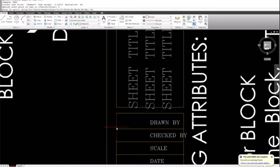
How to develop a title block with related attributes

This is an exclusive CAD video on for AutoCAD users. This CAD tutorial will provide you some useful tips to develop a Title Block through related Attributes.

Ensure that the Titleblock is developed in the MODEL space, it is saved perfectly prior to place in it on a Paper Space.

Attributes refer to specialized text in block definitions to be applied as a generic placeholder for generally used text.

Ensure that the Titleblock is developed in the MODEL space, it is saved perfectly prior to place in it on a Paper Space.

Attributes refer to specialized text in block definitions to be applied as a generic placeholder for generally used text.

How to generate blocks with attributes:

1. Draw the geometry as it can be done for any other block
2. Specify attributes
3. Specify the block. While choosing objects for the block, initially select attributes and in order of entry.
4. Put in the block into a drawing.


How to develop a title block with related attributes

~~~~~~~~~~~~~~~~~~~~~~
Published By
Rajib Dey
~~~~~~~~~~~~~~~~~~~~~~

Thursday, March 3, 2016

Improve your CAD workflow with TurboCAD Pro 2016 and TurboCAD Pro Platinum 2016

IMSI/Design recently launched both TurboCAD Pro 2016 and TurboCAD Pro Platinum 2016. A new feature video may be viewed at:


TurboCAD Pro Platinum 2016 can professional mechanical design process to the next level. This newest version of CAD software contains some outstanding features like superior 3D Blending, 3D Law tools and Point Cloud support.

TurboCAD Pro 2016 and TurboCAD Pro Platinum 2016 offers the following new and enhanced features:

3D MODELING / MECHANICAL

Superior Blending Functionality – With new 3D Fillet Blending options, it becomes easier to generate organic and rational. The limits of the fillet can be easily managed through 2D elements which are included in new Holdline Blend.

New Bend to Path and Part Tree operation can bend An ACIS solid object on a line, arc, or curve can be curved with new Bend to Path and Part Tree functions.

New Curve from Law tool develops a 2D, 3D curve with Laws that is formed parametrically. The developing curve is applied with the Graphic on Path tool, in Sweeps, etc.

New Surface from Laws create totally a new parametric surface object with formula.

New Warp Entity by Law can warp an accessible 3D solid on the basis of applying a formula.

New Offset with Laws restructures the developing offset object on the basis of applying a formula.

New Extract Entity facilitates removal of edges and faces out of a solid body with or without an offset. Offset sheet faces loops, and other excavated objects are utilized with other tools like sweep. There are various options like extract edge from body, extract/offset face from solid, remove open gap from sheet body, and offset face/planar face loop.

New Imprint Edge marks edges into Faces and segregate them into different areas each of which contains its own material.

For more features, go through www.marketwired.com

To get more updates or download a 30-day trial, as well as upgrade online, please visitwww.TurboCAD.com or call IMSI/Design at 1.800.833.8082 (+1.415.483.8000).


~~~~~~~~~~~~~~~~~~~~~
Published By
Rajib Dey
~~~~~~~~~~~~~~~~~~~~~

Friday, January 29, 2016

Brief Overview of Model Based Definition (MBD)

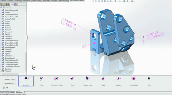
MBD represents model-based definition. MBD offers similar functionalities of PIM, or product information modeling. It offers unconventional way to dimension parts in both 2D and 3D.

It is the procedure of applying various 3D models like solid models, 3D PMI and related meta data inside any CAD software to offer specifications for specific components and product assemblies. There are various kinds of information in MBD which range from geometric dimensioning and tolerancing (GD&T), component level materials, assembly level bills of materials, engineering configurations, design intent, etc.

MBD facilitates to put both traditional and GD&T dimensions on the 3D model itself throughout the design phase. The engineer or designer can arrange these dimensions on the model for diversified applications.

Modern 3D CAD applications take into account the inclusion of engineering information like dimensions, GD&T, notes and other product details inside the 3D digital data set concerning components and assemblies. MBD applies such attributes to organize the 3D digital data set as the basis of these specifications and design authority for the product. The 3D digital data set may comprise of adequate information to manufacture and examine product devoid of any engineering drawings.

In several cases, applying some information out of 3D digital data set (e.g., the solid model) facilitates fast prototyping of product through different methods like 3D printing. A manufacturer can supply 3D digital data directly to manufacturing apparatuses like CNC machines to manufacture final product.

To learn more, go through the following exclusive article on MBD

Model Based Definition

~~~~~~~~~~~~~~~~~~~~~~
Published By
Rajib Dey
~~~~~~~~~~~~~~~~~~~~~~

Thursday, April 30, 2015

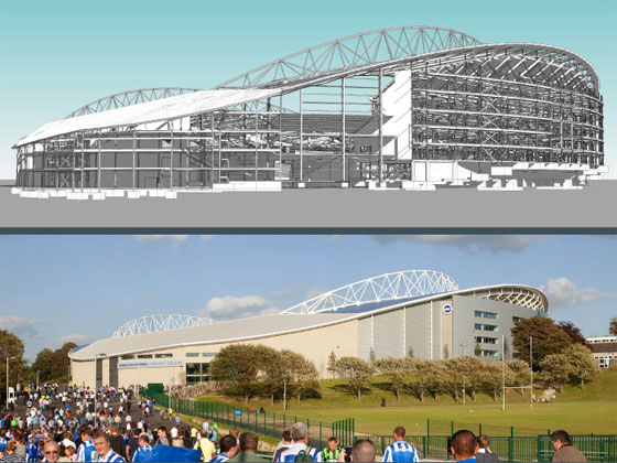
AEC firms can enjoy superior object based cad modeling with Renga Architecture from Ascon group

Ascon group has recently introduced its avant-grade 3D cad package alias Renga Architecture for AEC design. It is a solitary tool that integrates the ease of object-based Cad, 3D direct modeling and clarity of 2d drafting.

Renga Architecture is specifically designed for fixing diversified issues related with design and construction.

With this newly launched software, the users will not be liable for outlying reference materials as well as nonexistent element configurations rather than the users will get the ability to produce new building designs devoid of encountering any difficulties.

By applying Renga Architecture, the designers and architects can perform in an unconstrained 3D workspace as well as produce architectural projects instantly through various 3D design elements like slabs, walls, columns, windows, and roofs. With its in-built style editor and model explorer, Renga Architecture empowers the users to make design of the buildings by means of complicated architectural forms and resolve non-standard problems.

Besides, generating realistic 3d models, Renga Architecture also creates data models of buildings by assigning information concerning cuts, facades, levels, and lots other.

With the full-scale (1:1) 2D editor contained in Renga Architecture that works in drawing mode, the users can insert necessary graphics to drawing layouts by hand (lines and arcs, hatches and fills, elevation marks and sections, and dimensions). Drafting views are linked with the 3D model, and for any modification to the model, the geometry of the layouts is instantly updated.

Given below some striking features of Renga Architecture :-

  • It comes with an indistinct color spectrum, a well organized model disposition in 3D space, a flexible navigation system, and some useful commands categorized by function.
  • Realistic visualization with HBAO+ technology from NVIDIA Corp and horizon-Based Ambient Occlusion involving proper shading and refined shadow.
  • Imports & exports various industry recognized file formats.

The Renga Architecture is compatible with various formats like ifc for BIM data exchange, .dxf for CAD drawing exchange, .obj and .3ds for output to sophisticated rendering and animation software, .csv for output to data processing, .stl for 3D printer output.

The users can download a free 60-day trial version of Renga Architecture from their existing website atrengacad.com/en

Ascon group has recently introduced its avant-grade 3D cad package alias Renga Architecture for AEC design.
Image Courtesy: ascon.net
~~~~~~~~~~~~~~~~~~
Published By
Rajib Dey
~~~~~~~~~~~~~~~~~~

Tuesday, March 3, 2015

CCE launched EnSuite compatible with ACIS, Rhino, SketchUp and SOLIDWORKS 2015

CCE launched EnSuite compatible with ACIS, Rhino, SketchUp and SOLIDWORKS 2015
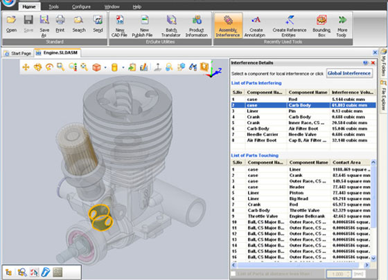
CCE, the reliable solution provider in various engineering software, just launched EnSuite software that can be applied to view and convert 3D CAD data.


The EnSuite is mainly used to convey and leverage cad data to everyone belonging to outside of engineering/design which range from sales/marketing, purchasing, quality, estimation, manufacturing, packaging, and customer service and others.

This newest engineering software is compatible with Rhino, ACIS and Sketchup. EnSuite contains the following exclusive features :

  • Viewer application is improved as the users now will be able to open, view, and convert models generated through SOLIDWORKS 2015 and Parasolid v27.0 as well as export any CAD model to the Parasolid V27.0 file.

  • View all the most important native CAD, Standard formats and Visualization and Point Cloud files under one viewer, self-governing of the source CAD system.

  • Evaluate and query data instantly from CAD files through simple easy-to-use productivity tools ranging from distance measurements, calculating mass properties, bounding volumes, BOM, and lots other.

  • Distribute any CAD Files, Markups, and reports with your extensive enterprise, with the help of top-notch translators, collaboration tools, and a 3D PDF generator.

  • You can computerize designs, processes, incorporate internal systems, and combine PDM/PLM/ERP.

  • The users will get the ability to view and transform part and assembly documents generated through ACIS, Rhino (.3dm), and SketchUp (.skp, .skb) formats.

  • User experience becomes better as the user-interface now supports any monitor resolution.

The users having active subscription, will be capable of accessing the software at free of cost.


CCE, the reliable solution provider in various engineering software, just launched EnSuite software that can be applied to view and convert 3D CAD data.
Image Courtesy: www10.mcadcafe.com


~~~~~~~~~~~~~~~~~~
Published By
Rajib Dey
~~~~~~~~~~~~~~~~~~

Wednesday, January 14, 2015

Some industry recognized BIM terms to execute a BIM project

With the advancement of Building Information (BIM), several new technical terms and keywords are included in it. But these BIM terminologies may not be always understandable by the professionals associated with construction industry. Given below the extensive lists of some useful BIM terminologies and their descriptions.

1. 4D, 5D, 6D, 7D: BIM gradually evolves from 2D CAD to 3D CAD. Now there are additional dimensions which are used for connecting the BIM model intelligently with time, cost, and schedule-related information. BIM can integrate 4D (time) and 5D (cost) virtual modeling of buildings, and all facets of life-cycle facility management (6D).

2. Asset Information Model (AIM), Building Information Model (BIM), Project Information Model (PIM): Besides, Building Information Model, there exist Asset Information Model (AIM) and Project Information Model (PIM). An Asset Information Model (AIM) refers to a model that accumulates the data & information required to support asset management i.e. for the operation of an asset. ‘Asset’ information model is assigned to the identical model post-construction. The ‘asset’ can also denote to civil engineering and infrastructure work.

Project Information Model (PIM) is the information model that is built up throughout the design & construction stage of a project.’ The necessity for the Project Information Model is defined in Employer’s Information Requirements (EIR) as well as at Level 2. It is expected to include a federated building information model, non graphical data and associated documentation.

The project information model is built up gradually, first like a design model and then a ‘virtual construction model involving all the objects to be manufactured, set up or assembled.

3. BIM execution plan (BEP): The BIM Execution Plan (BEP) is based on PAS 1192-2. It is one of the most crucial constituent of any successful BIM project. It describes the predictable BIM deliverables and directs the coordination of the project teams.

There are two types of BEP ranging from ‘pre-contract’ BEP & post-contract’ BEP. A pre-contract BEP is set up by potential suppliers, defining their projected approach, capacity and aptitude to meet up the Employer’s Information Requirements (EIR). Alternatively, it is equivalent to ‘contractor’s proposals’ in a Design & Build contract). Post-contract BEP defines how the information necessary in the Employer’s Information Requirements will be supplied.

4. CIC BIM protocol: It is an additional legal agreement intended for construction clients and contractor clients. The Protocol is a vital standard document that offers the legal framework in the application of BIM working methods in a project. The Protocol is designed to be applied in all common construction contracts and compatible with BIM working at Level 2. The protocol focuses on the detailed obligations, liabilities and associated limitations on the use of the models by the employer and the contracted party to allow collaborative working and at the same time protecting intellectual property ownership and legal responsibility discrimination amid those associated with the project.

5. Clash rendition: As per definition of PAS 1192-2:2013, Clash Rendition (CR) refers to rendition of the native-format model file to be purposely applied for spatial coordination methods. It is applied to attain clash avoidance or for clash detection amid structure and services as well as Building Information Models set up by diverse disciplines. The advantage of clash rendition is to minimize errors, and therefore costs, pre-construction commencement.

6. Common Data Environment (CDE): The Common Data Environment (CDE), is a central information storehouse for the project and it is utilized to gather, manage and distribute documentation, the graphical model and non-graphical data for the entire project team. It facilitates the project team to get rid of the repetition & mistakes. Cloud storage is a recognized method of providing a CDE. The purview and requisites for a CDE are described in PAS 1192-2.

7. Construction Operations Building Information Exchange (COBie): COBie is a data format that consists of a subset of the information available in the building model that focuses on distributing building information not geometric modeling. It is directly connected with building information modeling (BIM) approaches to design, construction, operation and management of built assets, refurbishment or demolition etc.

COBie facilitates to capture and record vital project data at the starting point together with equipment lists, product data sheets, warranties, spare parts lists, and protective maintenance schedules.

The Government’s Level 2-mandated requirement is for COBie-compliant information exchange. BS 1192-4 forms best practice for the execution of COBie.

8. Data drop: Usually, data drops are coordinated to the project phases, and the essential information reveals the level of development that the project should be accomplished by that phase. The RIBA Plan of Work suggests 6 data drops aligned with the phases like design brief, concept, design development / technical design, production information / tender documentation, practical completion, post-practical completion.

9. Data Exchange Specification: It refers to a specification for electronic file formats applied in switching over digital data connecting diverse BIM software applications. It also smooths the progress of interoperability. As for instance IFC and COBie (see above). PAS 1192-2 outlines information exchange activities.

10. Federated model: This is, basically, an integrated Building Information Model that is assembled by merging various diverse models into a single one. Alternatively the model can be imported into another for collaborative working.

A single federated model is ideal for design co-ordination, conflict resolution, approvals processes, design development, estimating etc. Here the individual models do not interrelate; they contain clear authorship and stay separate. So, the liabilities of the creators of the separate models remain unchanged by their integration into the federated model.

11. Government Soft Landings (GSL): The term "soft landing" already subsists in some portions of the construction industry and it imitates the requirment for moving smoothly from the design and construction stage to the operational stage of a built asset.

The motto of GSL is to minimize costs (capital and running) and enhance performance of asset delivery and operation, and is supported by the application of a Building Information Model. The following are some exclusive features:

  • BIM is projected to be applied more and more as a data management tool to make the briefing process easy and simple.
  • Post Occupancy Evaluation is executed, to assess and to make the performance of the asset better as well as be trained for the future.

12. Industry Foundation Class (IFC): IFC is an object-based format, to enable exchange of information between different software. Developed by ‘buildingSMART’, a global alliance specialising in open standards for BIM, IFC is an official standard, BS ISO 16739, and contains geometric as well as other data.

13. Information Delivery Manual (IDM): To reap the full advantages of BIM, information should be accessible when it is required and to a superior quality.

This can be obtained through an Information Delivery Manual that recognizes the different construction procedures, and the information necessary at every phase. ISO 29481-1 denotes a methodology for the format of the IDM.

IDM also outlines one part of the BuildingSMART interoperability model; the other two parts range from the Data Dictionary (mapping alternative terms for common elements) and IFC .

14. Information Manager: To implement the CIC BIM Protocol, it requires employing an ‘Information Manager’ by the employer. This is, basically, a project manager liable for dealing with the delivery of the asset through BIM processes and methods. This is anticipated to form the part of an extensive range of responsibilities under an existing appointment and is executable either by the Design Lead or the Project Lead.

Some industry recognized BIM terms to execute a BIM project

Image Courtesy: www.kssgroup.com

Ref: thenbs.com

~~~~~~~~~~~~~~~~~~~
Published By
Rajib Dey
~~~~~~~~~~~~~~~~~~~
Wednesday, December 10, 2014

Convert the photos/scans into high quality 3d meshes with Autodesk’s project momento

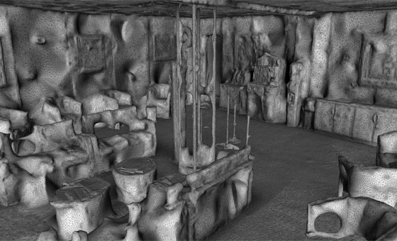
Autodesk has tied a knot with Artec to incorporate Artec’s series of industrial scanners with Project Memento. Project Memento is a free preview of Autodesk’s Labs technology that offers a streamlined solution for dealing with enormous meshes produced through reality capture systems like scanning or photogrammetry. With Project Memento, one can transform any pthotos, scans into super quality 3d meshes which can be cleaned up, fixed and optimized for digital application or fabrication. One can get rid of the time consuming practice for processing and organizing meshes created from reality capture sensors.

Both are also experimenting to facilitate Eva and Spider models to produce scans directly to Autodesk’s Project Memento for mesh and modeling work without any difficulty.

A forum is formed for generating and distributing very big 3D mesh models, simplifying the process to use those models in workflows which cover other Autodesk 3D modeling tools like Inventor or AutoCAD.

The engineers will be capable of applying the Artec scanners and the Project Memento service to scan a manufactured component and evaluate the 3D scan to the original 3D CAD model to analyze how the unit degenerates over time.


Get more updates

3d meshes with Autodesk’s project momento

Image Courtesy : www.cadlinecommunity.co.uk

~~~~~~~~~~~~~~~~~~~
Published By
Rajib Dey
www.bimoutsourcing.com
~~~~~~~~~~~~~~~~~~~

Sunday, December 7, 2014

parts4cad is the newest application for product manufacturers to browse numerous 3d cad models

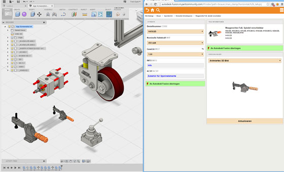
The users of Autodesk Fusion 360, a cloud supported design and planning software, can now explore and obtain numerous 3d CAD models out of 400 certified supplier & manufacturer catalogs with the newest application alias parts4cad launched by CADENAS. The users will be able to build up their models according to their choices as well as incorporate them directly into existing designs in Autodesk Fusion 360.

CADENAS is the most recognizedsoftware developer in the field Strategic Parts Management and parts reduction (PARTsolutions). The parts4cad contains a wide array of simple parts like fasteners and nuts over casters, profiles and fittings up to composite assemblies like pumps, cylinders and gears.

Autodesk Fusion 360 is a cloud based 3DCAD/CAM tool that can streamline the industrial and mechanical design, collaboration, and machining processes. The Designers and engineers can easily produce their product ideas in the cloud in 3D in conjunction with others they work on it.

The users can access Autodesk Fusion 360 at any time and from any remote location through any mobile gadget or internet browser.

The part4cad app for Autodesk Fusion 360 is priced at 7.99 and is available in Autodesk exchange apps.

For getting more updates, send mail to support@cadenas.de

parts4cad is the newest application for product manufacturers to browse numerous 3d cad models

Image Courtesy : apps.exchange.autodesk.com

~~~~~~~~~~~~~~~~~~~
Published By
Rajib Dey
~~~~~~~~~~~~~~~~~~~
Monday, November 24, 2014

Live Demo of GstarCAD 2015 beta

GSSOFTgroup presents an exclusive video presentation that focuses on the fundamentals of GstarCAD 2015. GstarCAD is a DWG compatible 2D and 3D Cad software.

The beta version of GstarCAD2015 is available in the market with some advanced features and functionalities to streamline your design process with fewer commands.

GstarCAD2015 contains some exclusive features like PDF Underlay, .Net Framework Support, Improved Interface (a new theme interface with a customized ribbon), Barcode & QR Code, Sheet Set Manager, Cloud Storage. Besides, there will be other significant enhancements like no lag with Pan and Zoom in/out operations, the layout switching speed is boosted specifically amid various viewports in a single layout.

Download a 32 bit and 64 bit free trial.


For more information, visit www.gstarcad.net/2015beta.html.

~~~~~~~~~~~~~~~~~~~
Published By
Rajib Dey
~~~~~~~~~~~~~~~~~~~
Sunday, November 23, 2014

Revit Architecture Creating 3D Views

Whether its housing projects, light industrial, factories, small offices, retail, mixed use or even small scale urban planning, there is a 3D CAD and BIM option everyone.

Even product manufacturers can use the 3D tools to design products and release them in object libraries for designers and end users to download and insert into BIM models.

From conceptual design, land evaluation to construction cost estimating, there is a software package included that will do the job at hand. In addition, all for one low cost – for everything.


~~~~~~~~~~~~~~~~~~~
Published By
Rajib Dey
www.bimoutsourcing.com
~~~~~~~~~~~~~~~~~~~

Sunday, November 16, 2014

aSa ProRebar - 3D CAD "BIM" Software for Construction Industry

This the software for civil engineers, civil engineering cad, cad detailing software, 3d cad software, bim software for constructions and building design.


3D CAD software innovations: Autodesk’s Digital Prototyping tools help engineers and designers experience their 3D CAD designs virtually, before they are built. By connecting every phase of your design process through a single digital model, our Digital Prototyping solutions let your teams test and optimize 3D CAD designs, helping to drive innovation, achieve higher quality, and speed time to market.

Our Building Information Modeling (BIM) software gives designers and engineers an integrated way to explore a project’s key physical and functional characteristics digitally. Using an intelligent 3D model to inform and communicate project decisions, our BIM solutions deliver insight and business value for building design, construction, infrastructure, and utilities projects.

Featured 3D CAD software: Whether you design buildings, products, or roads, or you are learning to transform your designs from 2D to 3D, there’s an Autodesk 3D CAD software product for you.


~~~~~~~~~~~~~~~~~~~~
Published By
Rajib Dey
~~~~~~~~~~~~~~~~~~~~

Friday, October 10, 2014

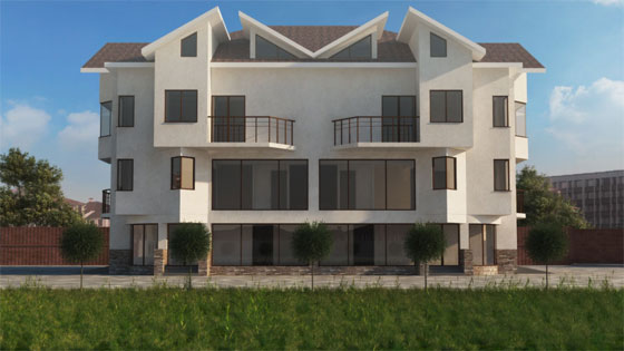
How to create an attractive gable end on a sloped roof with AutoCAD 3D

Mohammed Sabeer, a promising CAD Designer and Multimedia Trainer, has presented a nice video tutorial that analyzes how to make an attractive gable end on a sloped roof with the help of AutoCAD 3D. One can get familiar with several solid editing tools useful for any modification based on edge, face and body levels of a 3D solid.


Associated files necessary for applying this tutorial:-

2D Elevation drawings: www.dropbox.com

3D Drawing file to start the tutorial: www.dropbox.com

Completed 3D drawing file with porch: www.dropbox.com


~~~~~~~~~~~~~~~~~~~
Published By
Rajib Dey
~~~~~~~~~~~~~~~~~~~