adsense analytic

Showing posts with label Cad design. Show all posts

Wednesday, February 20, 2019

Advance Steel 2019 launched by Autodesk

Autodesk launched Advance Steel 2019, the most updated version of it’s structural steel detailing software. Given below, some exclusive features of the software.

1 – Improved interoperability with Revit 2019: The Advance Steel 2019 Extension for Revit 2019 transmits steel members and steel connections to Advance Steel 2019. The parametric steel connection is transmitted among the two products as well as individual components of custom connections like plates, bolts, anchors and welds. It will facilitate the steel detailers and fabricators to optimize the steel model designed in Revit.

2 – Improvements with migrate custom settings tool: The Migrate Custom Settings tool creates a modern and informative interface for migrating the custom settings and files from a earlier release to Advance Steel 2019. It facilitates recognizing customized settings and selecting which ones should have been migrated.

There are more migration options with customized settings like mapping definition, customized symbols, approval comments and status, and much more.

3 – New tool for fabricated anchors: Advance Steel 2019 contains a new dedicated “Bolt cage” tool (accessible in the Connection Vault) to add customized fabricated anchors to your base plates.
With the properties dialog, it is possible to identify these custom anchors with different shapes, sizes, complete with Tie Bars/Tie Plate and Washer possibilities.

There exist total 11 variations along with Rectangular, Triangular and Circular options for arrangements.
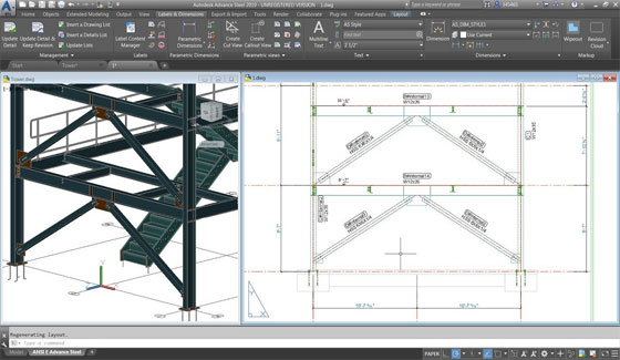
4 – Display horizontal grid lines on elevation views: If there are grid lines in your 3D models on distinct levels, it is possible to illustrate these grid lines on the elevation views of your drawing.
For that, it is required to activate the default “Display horizontal grid line in details” option that is available in the Management Tools, prior to generate the view on the drawing.

While adding a vertical dimension to this grid line on your drawing, one will be able to snap to “Preferred for manual dimensions” snap point to obtain smart dimensions which are modified automatically if the dimensioned grid line gets moved in the project.
5 – Enhanced drawing update behavior: In Advance Steel 2019, the drawing update behavior is improved for smart dimensions. In this newest version, smart dimensions stay in exact location at the time of updating a drawing.
Besides, the compass symbol stays in exact location and retains the style assigned to it when the drawing is updated.
Download a free trial version of Advance Steel 2019 www.autodesk.com
Advance Steel 2019 launched by Autodesk
~~~~~~~~~~~~~~~~~~~~~~~~
Published By
Rajib Dey
www.bimoutsourcing.com
~~~~~~~~~~~~~~~~~~~~~~~~

Wednesday, February 6, 2019

Simplify Revit Pipework with newly launched MEPcontent Plugin

The MEPcontent product library has introduced a new Revit plugin: the Raccorderie Metalliche Product Line Placer. With this plugin, the users will be able to design with Raccorderie Metalliche metal projects more uniformly within Revit.

MEPcontent stands for an app and plugin library for engineers in the mechanical, electrical and plumbing fields, which known as "the largest BIM library for MEP engineers."

Basically, it is compatible with part-manufacturing companies like plumbing manufacturer Raccorderie Metalliche to develop manufacturer-specific content.

The Product Line Placer functions directly on top of Revit. By applying this plugin, the users don’t have to choose the proper pipe fittings for the job manually rather they have to click and draw, and the exact fittings will be added automatically.

They will be now able to draw flexible pipe systems with special bends to facilitate them drawing in each direction, or simply switch to create advanced connections with real-world fittings inspite of Revit custom fittings. Lastly, the users will be able to work with in-app predefined schedules and order required items directly from inbuilt material lists to streamline the design-to-fabrication process.

While the plugin includes the localized content for Italy, France, Belgium, Germany, the Netherlands, and the United Kingdom, it can also be utilized outside of these locations. And, while its primary selling point is pipe design, it can also be utilized for ball valves, draw-off valves, bends, compensators, reducers, and flanges.


MEPcontent is specifically designed for MEP engineers to provide practical, flexible and incessantly innovating solutions.
To download the plugin, click on the following link mepcontent.com
Simplify Revit Pipework with newly launched MEPcontent Plugin

~~~~~~~~~~~~~~~~~~~~~~~~
Published By
Rajib Dey
www.bimoutsourcing.com
~~~~~~~~~~~~~~~~~~~~~~~~

Wednesday, January 9, 2019

New upgradation to Revit software add-ons developed by Ideate

Ideate Software, a veteran Autodesk Developer Network member, upgrades its Revit software add-ons with new features.


Given below, the details of new features :-
Ideate BIMLink

• Capability to edit data in the program; it does not require to export it to Excel initially.
• Capability to export metric units with the predictable Excel formatting for German customers
• Capability to edit the revision sequence of a revision cloud
Ideate Explorer
• Option to pre-define the significance of all 915 Revit warning types
• Capability to look for particular warnings and edit several warnings at same time
• Option to get warnings data only when the Warnings tab remains active
• Capability to view when a project has surpassed a certain number of warnings
IdeateApps
• Ideate ReNumber is now compatible with multi-category rules
• Ideate ViewCreator deals with visibility and graphic override conditions in an efficient manner while replicating plans by level

Ideate Sticky
• Capability to shift or rename project folders in Windows Explorer and sustain Ideate Sticky pathing
• Capability to avail Excel files which are part of an Autodesk BIM360 project
• Some previously unsuitable Excel files are now consistent

New upgradation to Revit software add-ons developed by Ideate
~~~~~~~~~~~~~~~~~~~~~~~~
Published By
Rajib Dey
www.bimoutsourcing.com
~~~~~~~~~~~~~~~~~~~~~~~~

Friday, November 30, 2018

Some useful tips to draw front elevation in AutoCAD

In this autocad video tutorial, you will learn some useful tips to draw front elevation of any building.

Once a elevation line is drawn, it is necessary to extract an elevation from the elevation line and the objects picked up in the building model.

As soon as a 2D elevation is created, the object produced is a 2D Section/Elevation object. Both 2D sections and elevations contain the equivalent object type and style.

Prior to generate an elevation, thaw and activate all layers of objects in the building model that should be contained in the elevation. The Objects on layers which are off or frozen cannot be segment of the selection set for the elevation. To make the performance better, deactivate the layers of the objects that should not be contained in the elevation.

2D Elevations: 2D elevations are produced by drawing an elevation line in front of a number of objects and then generating a 2D elevation object out of them. The elevation object is drawn devoid of hidden and overlapping lines.

It is possible to edit a 2D elevation by modifying its object display properties or its style display properties. The 2D elevation style facilitates the users to include display components to the display illustration of the elevation and develop rules that assign various parts of the elevation to several display elements.

The visibility, layer, color, linetype, lineweight, and linetype scale of every elements can be easily managed. It is also possible to assign a material like a brick or concrete hatch, to individual components of the object or the style. Furthermore, you can use linework editing commands to assign lines in a 2D elevation to several display elements, and combine geometry into a 2D elevation. The users can dimension 2D elevations.

3D Elevations: 3D elevations are produced by drawing an elevation line in front of a number of objects and then generating a 3D isometric elevation object out of them. The styles are not employed in 3D elevations.

The display of subdivisions inside 3D elevations can be managed easily. With the use of the Hidden Line Projection command, the users can generate 2D hidden line projections of any view of the 3D elevation that can be exploded and edited or hatched.

To learn the tricks to draw front elevations in AutoCAD easily, go through the following video tutorial.

Some useful tips to draw front elevation in AutoCAD

Read more
~~~~~~~~~~~~~~~~~~~~~~~~
Published By
Rajib Dey
www.bimoutsourcing.com
~~~~~~~~~~~~~~~~~~~~~~~~

Saturday, November 17, 2018

How AutoCAD is used for drawing column layout plan

Fundamentally, column layout plan is drawn with hand or AutoCAD. Given below, some useful step-by-step guidelines for column layout drawing with AutoCAD.

The following steps are involved :-


1. Select Column Shape: Initially, select the column shape. Several types of column shape are applied in diverse structures which range from circular, rectangular, box type column. Hence, it is important to select the column shape beforehand.
2. Draw the Column: As soon as the column shape is selected, then draw the column by applying the commands as rectangle (rec+Enter) or circle(c+Enter).
3. Settle the Column Location: Placement of column is considered as the most crucial part of a structure. The construction of a structure is based on the location of the column. Therefore, all the columns should be arranged at the exact location.
4. Settle the Grid Line: Gridline is a very significant segment of a structure since the position of all sections of the structure is set based on the grid line. The grid line should be drawn (horizontal & vertical) with line (l+Enter) or construction line (xl+Enter) command.
5. Numbering the Grid Line: The grid line should be numbered with a, b, c or 1,2,3 serially. It facilitates to trace something quickly and effectively.
6. Settle the Dimension with regard to Grid Line: Settle a dimension of all column relating to grid line with dim leaner (diml+Enter) command as except dimension it becomes complicated to trace the position of the column.
7. Numbering the Column: Locate a column to check that the schedule is not possible devoid of proper numbering. Therefore, the column should be numbered depending on its size & reinforcement.

How AutoCAD is used for drawing column layout plan
~~~~~~~~~~~~~~~~~~~~~~~~
Published By
Rajib Dey
www.bimoutsourcing.com
~~~~~~~~~~~~~~~~~~~~~~~~

Monday, November 5, 2018

How to create a 3D trash can model in AutoCAD

Musafu Cad comes with another informative autocad tutorial. In this tutorial, you will learn the tips to create the design of a trush can (garbage basket) in 3D with autocad. The tutorial is designed for beginner’s autocad users.

The dimension in the rendered image can be provided with texture editor. You need to click at left part (where TEXTURE EDITOR is inscribed). Subsequently, you have to edit sample size value or Offset.

The similar process should be followed with MATERIALS EDITOR. If you enquire about render size, you can perform that in Render presets manager, just type RENDERPRESETS.

To get online demonstration of the process, go through the following video.

How to create a 3D trash can model in AutoCAD

Read more

~~~~~~~~~~~~~~~~~~~~~~~~
Published By
Rajib Dey
www.bimoutsourcing.com
~~~~~~~~~~~~~~~~~~~~~~~~

Thursday, January 4, 2018

Reinforcement modeling in combined footing with Revit

In this Revit tutorial, you will learn how to use Revit for creating the model of reinforcement in combined footing.

There are various tools in Revit which can be utilized for modeling 3D concrete reinforcement in an advanced Building Information Modeling (BIM) surrounding. This presentation offers brief information on how to employ these tools in an efficient manner for the development of complete, detailed, and more accurate reinforcement designs.

The reinforcement tools can also be utilized to add reinforcement, like rebar, reinforcement bars, or fabric to valid hosts, like concrete columns, beams, walls, foundations, and structural floors.

Watch the following video tutorial to learn creating model of reinforcement.

Read more
~~~~~~~~~~~~~~~~~~~~~~~~
Published By
Rajib Dey
www.bimoutsourcing.com
~~~~~~~~~~~~~~~~~~~~~~~~

Wednesday, December 20, 2017

GRAPHISOFT introduces Grasshopper – ARCHICAD Live Connection 2.0 to simplify the BIM workflow

GRAPHISOFT recently launched Grasshopper – ARCHICAD Live Connection 2.0. This newest version facilitates the Rhino and Grasshopper users to be associated with a supreme BIM software package on both the Mac and Windows operating systems.

The combination of Grasshopper and ARCHICAD unveils new world of opportunities, by means of design, form-finding, optimization, and management of complicated projects.

With Rhino – Grasshopper – ARCHICAD (RGA) connections, the architects can experience the benefits of three powerful software environments to close the gap in the design process at the initial design phase. Algorithmic design workflows in Rhino and Grasshopper provide groundbreaking capabilities sustained behind the biggest community of algorithmic design enthusiasts and critical third-party developers expanding the Grasshopper development platform.

The latest 2.0 release of RGA radically develops new levels of smart workflows for ARCHICAD users and similarly Rhino and Grasshopper users in architecture. With the inclusion of the new “Deconstruct” function, the architects will be able to utilize their BIM models as a sort of building apparatus or “backbone” for their design; applying the RGA architects add algorithmic design logic to Grasshopper that can bring drastic changes to building elements (floors, roofs, walls, openings, etc) in due course.

Basically, this method allows the designers and architects to set up elementary design logic in BIM (in AC), for example the base geometry of the building, and spread that with intelligent design details to be available later but more significantly abides by changes in the core design.

Another useful feature is the capacity to employ Grasshopper to generate custom GDL Objects and then arrange them in their ARCHICAD project right away.

The newly-generated library parts are arranged in ARCHICAD’s Embedded Project Library and all the probable modifications in design which are created Grasshopper will be immediately delivered through the ARCHICAD project.

To get more information about RGA and the Grasshopper-ARCHICAD Live Connection, please visit: www.graphisoft.com

GRAPHISOFT introduces Grasshopper – ARCHICAD Live Connection 2.0 to simplify the BIM workflow


~~~~~~~~~~~~~~~~~~~~~~~~
Published By
Rajib Dey
www.bimoutsourcing.com
~~~~~~~~~~~~~~~~~~~~~~~~


Monday, December 4, 2017

Floorplanner is a handy program to draw floor plans online in 2D or 3D

This video tutorial provides the demonstration of Floorplanner.

It is a useful program that allows the users to generate their own floor plans online in 2D and 3D instantly.


Floorplanner contains various useful tools to recreate your home, garden or office with just few clicks of the mouse and deliver your plans with an extensive library of objects.
After producing the floor plan, it is possible to make the interior design better with the world's largest library of different types of furniture and items.
Floorplanner facilitates you to generate beautiful images and use them for marketing purposes, building work etc.

To learn various functionalities of the software, watch the following video tutorial.
To download the software, click on the following link https://floorplanner.com/

~~~~~~~~~~~~~~~~~~~~~~~~
Published By
Rajib Dey
www.bimoutsourcing.com
~~~~~~~~~~~~~~~~~~~~~~~~

Friday, December 1, 2017

Vectorworks Architect 2018 is just launched with some exciting features

Vectorworks is a leading BIM design tool specifically developed for all designers, architects, landscape architects, stage lighting designers, or anyone to design almost anything. The architects can utilize this all-in-one program to fulfill their requirements.

The architects can use it for different purposes like design concept, client presentations, final construction documents devoid of requiring any other programs. It performs as an in-depth presentation/drawing package as well as a highly sophisticated 3D modeler.


It is also an outstanding tool for just producing block layouts that transform into the buildings later on or making a simple design for a curved railing. To make improved designs, it is possible to generate shapes without limits with the help of subdivision modeling.
The most updated version is Vectorworks Architect 2018. It contains the following exclusive features :-
Several Drawing Views: The users can get several views of their on-going project simultaneously. Just click an icon then break up the screen as per choice. Now, it is possible to view the modification of the 3D model when the floor plan is revised. It is not necessary to switch alternatively among saved views at the time of updating and making changes.

Live Editing of Elevations and Sections: With Vectorworks Architect 2018, the architects will be able to edit Elevations and sections live. It is now possible to edit an elevation whereas actually looking at the elevation.
Resource Manager: With resource manager, the users can easily get access to numerous pre-drawn items. These may range from chairs, appliances, wall types or really anything. The users can create their own or import others.

Go through the following video, to be familiar with the new modeling features in Vectorworks Architect 2018.

Title Blocks: The title block feature becomes more comprehensive and automated. With this newest version, the users will be able to arrange their sheets according to their choice. Now the printed copies of the drawings can be delivered to the job site directly. And each one of those drawings normally contains a border and a title block with dates, names, responsible person and addresses.


~~~~~~~~~~~~~~~~~~~~~~~~
Published By
Rajib Dey
www.bimoutsourcing.com
~~~~~~~~~~~~~~~~~~~~~~~~


Thursday, November 30, 2017

nanoCAD 5.0 – The newest powerful CAD software

Nanosoft launched nanoCAD 5.0. It is a free, fully operative CAD software. After making registration and activating the software, the users can obtain a one-year renewable license and utilize the software for any purpose.

Once the software is installed, the users will be able to import drawing (DWG) files or develop new projects as well as export and share with others, devoid of any watermarks.


Top Three New Features of nanoCAD 5.0
nanoCAD provides support for DirectX graphics and it is now the standard for graphics performance for Microsoft Windows. DirectX is mostly recognized for gaming, but its graphics performance functions efficiently with computers and lower-end graphics cards. In nanoCAD 5.0, you can select which graphic library, OpenGL or DirectX, is considered as the perfect option for your video card. It can be accessed by opening the Options dialog box and selecting Graphic settings. (Image courtesy of Nanosoft.)
It is compatible with AutoCAD 2013/2014 version DWG files. nanoCAD can now read and write AutoCAD-supported DWG files which are well-suited with DWG files compatible with AutoCAD 2013.

Better object selection - The Quick Selection (QS) command is upgraded significantly and extended with a few vital capabilities. Now the users will be able to produce selection conditions for graphic primitives like arcs, polylines, splines and lines. The QS command in nanoCAD 5.0 also facilitates the users to produce selection conditions for complicated objects like tables, notes, dimensions and blocks.

The users can now add a block with .dxf file extension for greater adaptability.

nanoCAD products comprise of nanoCAD Plus, nanoCAD Pro, nanoCAD Mechanica, nanoCAD Construction, nanoCAD Construction Site.
To download nanoCAD 5.0, go through the following link nanocad.com

nanoCAD 5.0 – The newest powerful CAD software

~~~~~~~~~~~~~~~~~~~~~~~~
Published By
Rajib Dey
www.bimoutsourcing.com
~~~~~~~~~~~~~~~~~~~~~~~~


Tuesday, November 21, 2017

Up and Running with AutoCAD 2018: 2D Drafting and Design – An exclusive e-book

Elliot Gindis, the renowned cad professional and instructor has written an exclusive e-book called Up and Running with AutoCAD 2018: 2D Drafting and Design. The book is available in paperback version.

The book is enriched with stepwise instruction, illustrations and perceptive clarifications on the topic. The book focuses on the elementary concepts and practical use of AutoCAD in engineering, architecture and design.


The book is ideal for instructor-led classroom training, self-study, or as a professional reference. The book is specifically written to analyze 2D drafting and design in simple way and make it perfect for a one-semester course.
The book provides the following exclusive features :-
• Remove complications and diminishes AutoCAD to basic, easy to follow concepts
• Provides the guidance necessary for operating AutoCAD initially
• Documents all elementary commands, empowering the student what they should type in and how AutoCAD performs
• Comprises of new exercises and projects for the AutoCAD 2018 version
• Provides online bonus content on AutoCAD 3D fundamentals

The book contains 582 pages and written in English language.
To purchase the book online, go through the following link www.amazon.in
Up and Running with AutoCAD 2018: 2D Drafting and Design – An exclusive e-book

~~~~~~~~~~~~~~~~~~~~~~~~
Published By
Rajib Dey
www.bimoutsourcing.com
~~~~~~~~~~~~~~~~~~~~~~~~

Tuesday, November 14, 2017

How to convert any drawing to various image formats

This is an exclusive CAD video tutorial where you will learn how to transform your drawing into different types of image formats.
To accomplish this, you have to apply the following three commands :-

Display Image
JPGOUT
PLOT

Display Image – At first go to tools menu and from dropdown lists, click on display image and then click on save. Now save it to desktop or any drive. After saving it, there will be an option like JPEG image options where you will find quality and file size. Here put both of them to highest level and click ok. Now you will find the drawing has been converted to image.Image files are affixed to AutoCAD drawings. Alternatively stated, images do not turn out to be an essential part of a drawing. AutoCAD scarcely looks for images which are attached and loaded as necessary.
JPGOUT – In command line type JPGOUT, now choose the folder or drive where the image will be saved and save it.

PLOT – This command is used to plot a drawing to plotter, printer or file. To apply the command, go to command line and write PLOT and press enter.
Watch the video to obtain more detailed information.

Read more

~~~~~~~~~~~~~~~~~~~~~~~~
Published By
Rajib Dey
www.bimoutsourcing.com

~~~~~~~~~~~~~~~~~~~~~~~~

Thursday, November 9, 2017

BRE is going to launch revolutionary BIM DataBook for global BIM professionals

BRE has introduced a new BIM data product library set to provide a solution to the communication issues which arise while interchanging BIM models.

The new Templater tool will eliminate the mess as well as scarcity of interoperability that may arise while distributing standardised product information from BIM and related technologies. BRE Templater (with code by activeplan) will offer core building element definitions (like doors, windows, plasterboard, roof tiles etc.) and is based on international standards like IFC. DataBook is still in beta testing phase and expected to be launched in early 2018.


DataBook Product Library is totally free to use that facilitates the registered users to connect their BIM objects and relate data to a fixed manufacturers’ data source. DataBook offers plug-in functions for authoring tools with options to connect as well as include data on the basis of project phase and exact project roles. It will eliminate the accountability and risk for designers and constructors from employing editable BIM Library objects and at the same time offering them with the perfect manufacturer data required for giving response to the project requirements throughout the project lifecycle.
DataBook can easily control the information flow throughout the design and build process, devoid of the existing complicated geometry.

It will allow BIM to function for everyone, because presently lots of objects are modified manually when projects are transmitted among manufacturers, architects and contractors. It will save huge time and money.
DataBook records BIM Product Library that will function as an unchanging, state-of-the-art and universal data store for all BIM data.

DataBook is expected to be launched in early 2018.
www.pbctoday.co.uk

BRE is going to launch revolutionary BIM DataBook for global BIM professionals

~~~~~~~~~~~~~~~~~~~~~~~~
Published By
Rajib Dey
www.bimoutsourcing.com
~~~~~~~~~~~~~~~~~~~~~~~~

Tuesday, November 7, 2017

Shape – A new sketchUp-like .dwg-based conceptual modeling software will be launched soon

Belgian CAD developer Bricsys, is going to launch a new SketchUp-like .dwg-based conceptual modeling software known as “Shape”. Shape even begins with a human figure at the 0,0,0 coordinate point (origin) similar to SketchUp.

Shape is specifically developed to deal with the conceptual modeling phases of the architectural design process.

One can access this software for free early in 2018. Shape is a subset of BricsCAD, that adheres to the AutoCAD user experience intimately.
Shape comes with two unique command entry tools available in BricsCAD. The first is Quad cursor, an information resource that provides commands which fluctuate according to the location of the cursor and the current actions of the user. The second is Manipulator, a substitute cursor that arrives while moving objects, to set angles for easier location.
Shape can be used to quickly produce walls and other standard shapes of architectural conceptual design. There is no need for file conversion to employ Shape models in BricsCAD, AutoCAD or any other software that imports .dwg files.

The structural elements are intelligent, similar to other existing BIM editors. Walls, doors, windows and other structural elements transmit metadata of their definition, materials, etc. If the shape of an object is modified, the metadata and any related constraints are updated.

To gather more information, go through the following link aecmag.com

Shape – A new sketchUp-like .dwg-based conceptual modeling software will be launched soon

~~~~~~~~~~~~~~~~~~~~~~~~
Published By
Rajib Dey
www.bimoutsourcing.com
~~~~~~~~~~~~~~~~~~~~~~~~

Friday, July 28, 2017

Autodesk Revit 2018 Architecture Fundamentals - Imperial (1st Edition) – An exclusive reference book for Revit users

The Autodesk Revit software is a powerful Building Information Modeling (BIM) program that works the way architects think. The program streamlines the design process through the use of a central 3D model, where changes made in one view update across all views and on the printable sheets.

Autodesk Revit 2018 Architecture Fundamentals - Imperial (1st Edition) is an exclusive reference book for Revit professionals that briefly focuses on the Autodesk Revit functionality to be applied efficiently during the design process.

Initially, the book explains the user interface and basic drawing, editing, and viewing tools. Then you will be familiar with design development tools together with how to model walls, doors, windows, floors, ceilings, stairs and more. At last, you will be introduced with the processes to transform the model to the construction documentation phase.
The book will facilitate the students to generate complete 3D architectural project models and arrange them in working drawings.
The book includes the following topics :-
• Perception of the objective of Building Information Management (BIM) and how it is used with the Autodesk Revit software.
• Administering the Autodesk Revit workspace and interface.
• Dealing with the fundamental drawing and editing tools.
• Generating Levels and Grids as datum components for the model.
• Making a 3D building model involving walls, curtain walls, windows, and doors.
• Inclusion of floors, ceilings, and roofs to the building model.
• Generating component-based and custom stairs.
• Inclusion of component features like furniture and equipment.
• Arrangement of sheets for plotting with text, dimensions, details, tags, and schedules.
• Production of details.

Click on the following link to download the book www.ascented.com

Autodesk Revit 2018 Architecture Fundamentals - Imperial (1st Edition) – An exclusive reference book for Revit users


~~~~~~~~~~~~~~~~~~~~~~~~
Published By
Rajib Dey
www.bimoutsourcing.com
~~~~~~~~~~~~~~~~~~~~~~~~

Monday, April 10, 2017

How To Draw Circle With Various Methods In AutoCAD

This is an exclusive autocad tutorial where the autocad users can learn how to apply different methods in AutoCAD for creating the design of circles. The methods used here vary from radius method, diameter method, 2P (two points) and 3P (three points) methods. The autoCAD users can apply various circle commands.

2P means drawing a circle on the basis of two points on the circumference. 3P means drawing a circle on the basis of three points on the circumference.

3P Method: Initially go to the menu Draw>Circle>3 Points. Then the command prompt will send notification as _3p Specify first point on circle. This is just notifying you to select a point on the screen that will be your first point. Then AutoCAD will send notification to Specify second point on circle i.e. choose another point to draw your circle.


2P Method: This command is mostly effective while going to create circle tangent to arcs, lines or circles. As for instance, if there exist a line and an arc and it is required to produce a circle tangent and among those two objects

How to draw circle with various methods in AutoCAD

~~~~~~~~~~~~~~~~~~~~~
Published By
Rajib Dey
www.bimoutsourcing.com
~~~~~~~~~~~~~~~~~~~~~

Wednesday, October 19, 2016

Top Five Android Apps For AutoCAD Users

AutoCAD 360: AutoCAD 360 is a free mobile based app to view DWG. There are user-friendly drawing and drafting tools in this app which can be useful for viewing, generating, editing, and distributing AutoCAD drawings over web and mobile devices in anytime from any location. Make your site visits process easy with these robust drafting and editing tools.

Download from Google play store (AutoCAD 360)

DWG FastView-CAD Viewer: DWG FastView completely supports 2D/3D DWG drawings to open DWG drawings from Autocad, progeCAD, BricsCAD, ZWCAD efficiently as well as view CAD design like autocad drafting, revit blueprint and dxf.etc. Some exclusive features range from :-

Rapid formation, Free browsing and editing; No registration & Offline drawings; Support exporting to PDF, BMP, JPG and PNG, and distribute it to anyone freely; View Mode and Edit Mode fulfills various requirements; Useful and approachable technical support.

Download from Google play store DWG FastView-CAD Viewer

Learn AutoCAD For 2015: Learn AutoCAD 2015 Manual that covers the following topics :-

-basic learning autocad 2d
-diemension vecter drawing
-plot workspace
-presentation
-guide snap osnap
-more tutorial within this app

Download from Google play store Learn AutoCAD For 2015

CAD Reader-DWG/DXF Viewer: With CAD Reader-DWG/DXF Viewer-DWG/DXF Viewer on your phone or tablet, one will be able to view and label CAD drawings anytime from any location. CAD Reader-DWG/DXF Viewer makes your site visits easy by applying the robust tool available. Easily manage your job on the move and also connect with your partners at any moment with CAD Reader-DWG/DXF Viewer to view your CAD drawings.

CAD Reader-DWG/DXF Viewer provides various robust features and capabilities for free.

Download from Google play store CAD Reader-DWG/DXF Viewer

Planner 5D - Interior Design: Planner 5D is a user-friendly app that facilitates you to produce nice looking and convincing interior and exterior designs in 2D and 3D modes.

You can select from interior and exterior items from a wide-ranging catalog with the purpose of planning and delivering your home or any other space as per your requirement, and you can view what everything appears in reality by applying the Virtual Reality mode.

Download from Google play store Planner 5D - Interior Design

Top Five Android Apps for AutoCAD users

~~~~~~~~~~~~~~~~~~~~~~
Published By
Rajib Dey
~~~~~~~~~~~~~~~~~~~~~~

Thursday, June 23, 2016

FARO launched PointSense, VirtuSurv v17.0 Plug-ins for BIM and CAD users

FARO Technologies, Inc. has launched PointSense and VirtuSurv 17.0. Both are laser scanning plug-ins for the Autodesk environment that facilitate smooth integration with the current Autodesk 2017 product line.

With both the PointSense and VirtuSurv 17.0 programs, BIM-CIM CAD designers can obtain extensive set of tools to simplify the process for converting enormous point cloud data sets into intelligent 3D models.

Customers can opt for software modules which are equivalent to their particular workflows. These plug-ins are accessible for both AutoCAD and Revit.

PointSense for Revit 17.0 now offers support for “work-sharing” projects, assisting all BIM-CIM stakeholders to instantaneously apply PointSense on a common Revit project file. Besides, an improved wall-fitting tool facilitates the users to pull out walls out of point clouds devoid of scanning both sides of the wall.

Accessibility: PointSense and VirtuSurv 17.0 are available for instant delivery and a limited-time promotional offer, when assembled with FARO’s top-notch BIM-CIM Laser Scanner, is available until June 24.

For more information visit faro-3d-software.com


~~~~~~~~~~~~~~~~~~~~~~
Published By
Rajib Dey
~~~~~~~~~~~~~~~~~~~~~~

Tuesday, February 16, 2016

CAD blocks can save huge time & money in your cad design & cad drafting process

CAD blocks are also known as model libraries as well as standard part libraries or just blocks. These CAD blocks can be used to streamline the CAD drafting & designing process. A CAD block belongs to a named object, or group of objects, that is drawn in 2D or modeled in 3D and after that it is used to generate continual CAD content like drawing symbols, standard details, common parts or other objects operated constantly inside a drawing or model.


As for example there may be various doors inside the plan having identical type and size in a customary residential floor plan. CAD blocks are used to reprocess those doors rather than drawing a new one always. This results in saving huge time and money.

Benefits of CAD Blocks

Curtail Iterative Tasks — when the design team requires to utilize an object or part several times in a drawing, they should employ blocks. Blocks will save significant times while generating objects primarily as well as save huge time when modifications are necessary. As for instance, if it is required to modify the type of water closet utilized in all the bathrooms all through the building in a big commercial architectural floor, it is not necessary to modify each water closet one at a time. Just revise the block in Block Editor and the block will be automatically corrected in every allocated space in the drawing.

Accuracy — If you use a perfect CAD part or block, apply that similar CAD part or block all through a drawing or model. It will maintain reliability and reduce prospective errors originated from redrawing the item every time. Besides, if you are going to start the design with complicated parts, just download the required part or model directly from a manufacturer or supplier. Thus, you will get proper size and specification information to apply in your design.

Reduced File Sizes — File size is decreased through instancing content devoid of redefining object data for each instance, a block is applied. Just use your CAD program to obtain the insertion point and rotation by reprocessing the object geometry out of the original block. It can greatly optimize the performance while dealing with large projects.

Maintain Consistency — If you contain a series of CAD standards, make sure that all the drawings and models are perfectly demonstrated. If all your title blocks, plumbing fixtures, piping symbols and fasteners are shown systematically from one drawing to another, apart from which CAD user operated on them, it is a very crucial factor in improving the effectiveness as well as and minimizing the chances for error in your drawings.

Block Attributes — There are various types of metadata information known as attributes in the blocks. These may range from information like title block information, asset tracking numbers, or manufacturer information for example part number, model or weight. This data can be associated with an Excel database and extracted to generate reports, bills of material and schedules.


CAD blocks can save huge time & money in your cad design & cad drafting process

~~~~~~~~~~~~~~~~~~~~~
Published By
Rajib Dey
~~~~~~~~~~~~~~~~~~~~~