adsense analytic

Showing posts with label 3D model. Show all posts

Friday, July 12, 2019

Microcenter Group and Autodesk to make Partnership to offer training on BIM and CAD

MicroCenter Group ties a knot with Autodesk to provide advance education on Autodesk design application, BIM and CAD.

Renowned information technology solutions company MicroCenter Group has officially declared its academic joint venture with Autodesk.

The program will facilitate the formation of an Autodesk authorised learning centre, Design BIM Studio, and Certiport authorised test centre.

The purpose of this alliance is to reanalyze advanced education and work skills in Autodesk design applications, 2D and 3D CAD designs, infrastructure designs, building information model (BIM) and BIM co-ordination, 3D model and real-world visualization.

The collaboration provides more value to industry professionals who will opt for advanced education on Autodesk software applications through the Micro Training Center (MTC), a subsidiary of MicroCenter Group.

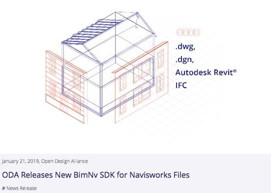
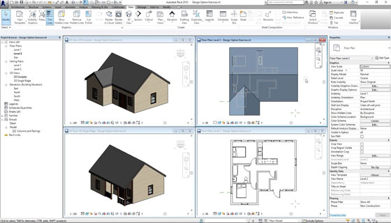
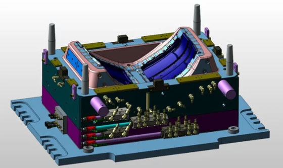
Courses will be conducted on AutoCAD, AutoCAD-Civil 3D and Map 3D, AutoCAD–Plant 3D, Revit Architecture, Revit MEP and Structural, Navisworks, Inventor, 3DS Max, Fusion 360 and Maya and Autodesk professional certification.

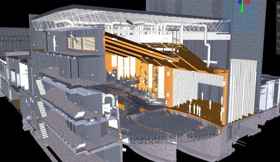
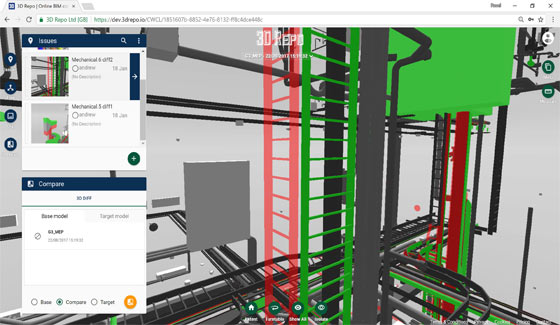
MicroCenter Special Projects Business and MTC will set up BIM design and BIM Education centre this year, to provide complete building information modelling and implementation services through the 3D laser scanning technology, for building, infrastructure and metro-rail projects.

BIM studio will arrange advanced and professional skills training to engineers, architects, industry professionals, educators, and students.

Esri and Autodesk work in tandem to mutually provide GIS and BIM across multi-disciplinary teams and project life cycles.

The objective is to maintain an integrated and collaborative workflow that progresses understanding of projects within the framework, and minimizes inefficiencies, data loss, and cycle times.

Designers and engineers will be able to get GIS content from ArcGIS Online into Infraworks via the Autodesk Connector for ArcGIS.

Content such as roads, pipelines, and electrical transformers will be directly imported depending on an authoritative, subsisting geographic system of record.

Read more

Microcenter Group and Autodesk to make Partnership to offer training on BIM and CAD

~~~~~~~~~~~~~~~~~~~~~~~~
Published By
Rajib Dey
www.bimoutsourcing.com
~~~~~~~~~~~~~~~~~~~~~~~~

Tuesday, June 4, 2019

OpenSite Designer is a powerful tool for BIM professionals

Bentley Systems just launched OpenSite Designer, its integrated application specifically designed for civil site and land development workflows over conceptual, preliminary, and detailed design phases.

OpenSite Designer accelerates BIM through widespread 3D site design, extending reality modeling of site conditions from drone imagery and scans, geotechnical analysis, terrain modeling, site layout and grading optimisation, stormwater drainage modeling and analysis, underground utilities modeling, detailed drawing production, and enlivened visualisations.

OpenSite Designer facilitates fast and recurrent conceptual design, maximizing contextual information acquired through point clouds, reality meshes, GIS, and other sources to improve conception of existing site conditions. Interoperating with PLAXIS and SoilVision, Bentley’s geotechnical engineering solutions, site plans can be better with new information about the active properties of soil along with bearing strength, stresses, and displacement.

With OpenSite Designer, users get the ability to generate intelligent 3D models with site information, terrain data, parking lots, building pads, driveways, sidewalks, parcel layout, and associated site features. In case of preliminary design, the site engineer can finish and rationally makes the layout greater even as depending on further automated optimizations, which fit together with the engineering changes. To finish the project’s digital workflows, OpenSite Designer totally supports the site engineer’s detailed design along with the production of all necessary project deliverables.

With OpenSite Designer, the site engineers can improve the civil site design from conventional 2D plans and profiles to a 3D modelling environment, ensuring proper analysis of hydraulics, geotechnical, geospatial, and earthworks. Integrating the analytics optimisation of Bentley’s SITEOPS technology, OpenSite Designer is the inheritor to the site design capabilities of Bentley’s PowerCivil, topoGraph, GEOPAK Site, InRoads Site, and MXSite.

To get more detail, click on the following link bentley.com

OpenSite Designer is a powerful tool for BIM professionals

~~~~~~~~~~~~~~~~~~~~~~~~
Published By
Rajib Dey
www.bimoutsourcing.com
~~~~~~~~~~~~~~~~~~~~~~~~

Thursday, April 4, 2019

How to manage projects with BIM efficiently

Building information modeling (BIM) process gains huge popularity among the architecture and construction industry. Since, BIM is extensively used by several architectural and engineering firms into their practice, it becomes difficult for the project managers to control the project teams employing BIM.

Given below, some vital tips to manage project with BIM in an efficient manner.

Recognize the method

BIM stands for a collaborative method of generating coordinated, internally logical and quantifiable information concerning a building with a central system of 3d models in spite of a separate set of 2d drawings. It is a new way of working that simplifies the workflow with an unified approach.

Know the competencies of the tool

A Revit model is much more than a 3d model, it contains a database of information which can be used for constructability analysis, quantity take-offs, performance analysis, facilities management and so on. Working in a model based framework makes sure greater precision; as components change in the plan, they proceed in elevations and sections. When the windows are provided in the exterior wall, window schedules are updated. Prompt 3d visualization facilitates taking decisions in advance. As a minimum, find out how to open, close and navigate through a model, cut sections and print drawings.

Follow the 60/40 rule
BIM workflow generally comprises of two steps: modeling and documentation. Accept about 60% of the time for modeling, rest for generating and annotating drawings. Set up design and documentation benchmarks and decide on the level of detailing for different elements before starting modeling. Should the model be applied for construction documentation or fabrication and assembly? Prior to add a wall, ascertain its width, make and fire rating. Fix the rules at the beginning.
Have a clash detection competition
A Revit model can easily determine the spatial clashes among different systems in the building, like ducts moving through beams or lights hitting sprinklers. It facilitates saving time and cost because of less errors all through the construction. While Revit facilitates fundamental diagnostics, software like Navisworks can recognize and document conflicts comprehensively. Arrange every other coordination meeting to be virtual, discuss with the model.
How to manage projects with BIM efficiently
~~~~~~~~~~~~~~~~~~~~~~~~
Published By
Rajib Dey
www.bimoutsourcing.com
~~~~~~~~~~~~~~~~~~~~~~~~

Wednesday, March 6, 2019

Details about Level of development (LOD) in BIM

Level of development (LOD) means a supposition with different definitions and executions. The level of development characterizes the content and reliability of BIM components at various phases or milestones. The “content” signifies geometric information, structured data and linked documentation.

The reliability signifies what has been utilized and to what extent the downstream users of the information can rely on the precision and quality of that content.


LOD is categorized as follow :-
LOD 100 – Concept Design
3D model of the building is formed to demonstrate the information on basic level. As a result only conceptual model can be produced in this phase. Several parameters ranging from area, height, volume, location and orientation are characterized.
LOD 200 – Schematic Design
General model where components are modeled with guess quantities, size, shape, location and orientation. Non-geometric information can also be added to the components of the model.
LOD 300 – Detailed Design

Exact modeling and shop drawing where components are characterized with certain assemblies, proper quantity, size, shape, location and orientation. Here, non-geometric information can also be added to the components of the model.
LOD 350 – Construction Document
It comprises of model detail and component which demonstrate how building components interacts with several systems as well as other building components with graphics and written definitions.
LOD 400 – Fabrication & Assembly
The components of the model are modeled according to certain assemblies with complete fabrication, assembly, and detailing information other than exact quantity, size, shape, location and orientation. Non-geometric information to the model components should also be added.
LOD 500 – As-built
The components are modeled similar to constructed assemblies for maintenance and operation. Other than actual and accurate in size, shape, location, quantity and orientation, non-geometric information is also added to the components of the model.
To get more detail information, go through the following video tutorial.


Video Source: Balkan Architect
~~~~~~~~~~~~~~~~~~~~~~~~
Published By
Rajib Dey
www.bimoutsourcing.com
~~~~~~~~~~~~~~~~~~~~~~~~

Monday, January 28, 2019

New ‘BimNv’ SDK for Navisworks Files launched by ODA (Open Design Alliance)

The Open Design Alliance (ODA), a trusted solution provider in CAD interoperability and component technology, introduced its new BimNv SDK (software development kit).
BimNv belongs to the industry’s first autonomous, cross-platform toolkit for dealing with Autodesk® Navisworks® files.

It is now possible to include Navisworks file support to the suite of BIM interoperability toolkits. The ODA members will now be able to import data from Navisworks files into any application, or visualize this data in 3d from desktop, mobile or web applications by applying complementary Visualize technology.
The ODA’s latest SDK facilitates the developers to read and interoperate with Navisworks files. Besides, Navisworks, IFC, Revit and .dwg and .dgn files are integrated in a 3D view and clash detection can be run on the model.

Besides, providing the support for Navisworks files, it is also possible to incorporate files of various formats to generate a whole-project view of a model. Supported formats comprise of .dwg, .dgn, Autodesk Revit® files, IFC, and more. Clash detection can be run on the combined model in 3D to identify interferences.

One can avail a free 60-day trial version from www.opendesign.com

New ‘BimNv’ SDK for Navisworks Files launched by ODA (Open Design Alliance)


~~~~~~~~~~~~~~~~~~~~~~~~
Published By
Rajib Dey
www.bimoutsourcing.com
~~~~~~~~~~~~~~~~~~~~~~~~

Monday, January 21, 2019

How to import AutoCAD files into Revit

In this exclusive Revit tutorial, you will get some useful tips to import DWG or AutoCAD files into Revit. You will be able to convert any AutoCAD project, 2d plans into a 3D model into Revit.

Initially, you will learn how to set up the file in CAD prior to put it on Revit to get rid of any trouble with the file for working with it. Then you will learn the proper procedure to import as well as how to perform all the setups, place it and lock in exact location.

Then, you will be guided to setting all visibility graphic and how to set up entire view to view your floor plan in AutoCAD properly as well as how to apply this plan efficiently to model your revit file.

To download the project file, click on the following link. www.patreon.com

How to prepare your DWG file :

1. Open the file in AutoCAD.
2. Verify xrefs (externally referenced DWG files). If some exist, connect them to the drawing, with the Insert option to get rid of excess layers.
3. Run SETBYLAYER to eliminate any color, linetype, or lineweight overrides from objects.

4. Run PURGE to eliminate any leftover layers, linetypes, blocks, and styles.
5. Freeze any unnecessary layers.
6. Apply SAVEAS to save a copy of the file in your “CAD Links” folder (or wherever your standard linked file location is).


To learn the complete method for importing CAD files to Revit, go through the following tutorial.

Video Source: Balkan Architect

~~~~~~~~~~~~~~~~~~~~~~~~
Published By
Rajib Dey
www.bimoutsourcing.com
~~~~~~~~~~~~~~~~~~~~~~~~

Wednesday, December 5, 2018

How to efficiently utilize design options in Revit

In this exclusive Revit video tutorial, you will learn how to apply the stunning design options tool in Revit to explore through various design options and use them in your 3d model. Test these design options and check how they perform devoid of saving individual files.


The users can access design options in the following two ways :-
From the Manage tab > Design Options (under Design Option Panel).

At the bottom bar of the Revit window, click the icon.
When the Design Options dialog box open, it is found that the dialog box is segregated into 2 parts. The white box on the left shows all the design options available for any project. In the right side, there are the editing tools like Edit, Option Set and Option which are utilized to produce the design options.
Edit – This option allows you to edit each option. There is another option alias Switch between Options to edit option quickly.
Option Set – It is a folder that retains all the options for a specific area of interest. As for example, one Option Set for “Office Suite” and another Option Set for “Cafeteria”.
Option – These are the options produced inside the Option Set. As for instance, inside the “Office Suite” set, there is Option A, B & C furniture layout design.

Note: There are numerous Option Set in the same view, but each view can only contain one Option.
Setting up Design Option
Initially, it is required to setup all the Option Sets and Options required, then assign the components in the existing model to the exact option. An analogy is to setup folder and blank files as a place holder primarily, then include components to the blank file later.
Step 1: Under Option Set, click “New”, it will generate first set of Design Options.
Step 2: Under Option, click “New”, it will generate first design option in the set. It is possible to produce as many Option as required within the equivalent set.
Note: Revit will not permit the users to make an Option unless an Option Set is made.
Reiterate the above steps as required to generate more Option Set and Options.
The Option with the word (primary) next to it is known as Primary Option. This is the default design that shows in your model. The users can choose any option as the Primary by clicking Make Primary (under Option).
To get more clear ideas, go through the following video tutorial.
How to efficiently utilize design options in Revit
~~~~~~~~~~~~~~~~~~~~~~~~
Published By
Rajib Dey
www.bimoutsourcing.com
~~~~~~~~~~~~~~~~~~~~~~~~

Friday, September 14, 2018

Kubotek3D Releases KeyCreator 2019

Kubotek3D, the leading solution provider of 3D mechanical CAD software, introduced the most updated version of KeyCreator CAD/ CAM software. KeyCreator 2019 offers crucial enhancements in graphics performance with large models, various productivity enhancements, updates to translators, and the accessibility of new CAD translators.

KeyCreator 2019 is specifically designed to improve complete performance and speed of graphics displays.

Given below, some exciting features of the software :-

Improved Graphics: KeyCreator 2019 comprises of a significant reconstruction of the internal data architecture applied along with the HOOPS engine component from Techsoft3D to render everything visible in the graphical viewport. It leads to significant 300% to 600% enhancement in frame rate speeds for models containing huge numbers of faces, especially for partial transparency.

Productivity Enhancements: Instant re-processing of model geometry is significantly improved by arranging DynaHandles in the commonly used file import and cut/copy/paste functions. It facilitates automatic in-process adjustment to the positioning, rotation, and scale with visual feedback devoid of a multi-step process or requiring to carry out a separate edit function.

The Bounding Box function is applied to produce a block to encircle selected objects, generally for modeling solid metal block and it is updated with automatic associative length, width, height dimension entities as well as support offset values to insert material around the selected objects.

Support has also been improved in surface modeling for dynamically expanding a surface and deforming a curve with various control point all together.

Updated CAD Translators: New CAD file import translators is available for the newest versions of JT and Solid Edge files are added to the Pro and Max levels in KeyCreator 2019. These translators are dependent on InterOp components from Spatial Corporation.

Furthermore, interoperability with other software is upgraded with the latest versions of 4 major CAD file formats:

1. Autodesk Inventor 2019
2. Dassault CATIA V5 R28 (R2018)
3. PTC Creo 5.0 (drawings)
4. Siemens NX 12 (PMI)


With several CAD products, large files are broken down with assemblies and layers to resolve graphics speed issues. The files that would otherwise jerk and struggle through dynamic rotation movement attempts are now completely incessant, and contain smooth movement navigating designs. It is now possible to instantly and easily view an entire project right away.

To get more details about KeyCreator 2019, visit kubotek3d.com

Kubotek3D Releases KeyCreator 2019

~~~~~~~~~~~~~~~~~~~~~~~~
Published By
Rajib Dey
www.bimoutsourcing.com
~~~~~~~~~~~~~~~~~~~~~~~~

Monday, September 10, 2018

Get better view of 3D BIM models on the construction site with new HoloLens OS update

The latest HoloLens OS update (RS4) offers some immense benefits for BIM Holoview users. The performance and projection stability are enhanced significantly as well as the memory capacity is also increased greatly.

It facilitates the users to enlarge the size of the Autodesk® Revit® and Navisworks® files that BIM Holoview handles. As a result, more building services and bigger areas can now be viewed.

This improvement supports the following two major features of BIM Holoview:

(1) Perfect location of models to within 2cm that allows visual inspection of the proper placement of structural components and services.

(2) The transparency mode that facilitates the layers of a building, and hidden structure and services to be visualized.

Due to design and construction faults, the non-residential construction industry has to loss approximately US $49 billion per year. The objective of BIM Holoview is to decrease these costs by around 50%.

So, the average savings for a construction company would be $1.4 million per year (and $24.5 billion for the industry overall). The users also get benefitted from elevated productivity because of the comprehensive understanding that viewing models on-site provides – evident in construction of the Park Hyatt Auckland.

To get more information, go through the following link forums.hololens.com

Get better view of 3D BIM models on the construction site with new HoloLens OS update

~~~~~~~~~~~~~~~~~~~~~~~~
Published By
Rajib Dey
www.bimoutsourcing.com
~~~~~~~~~~~~~~~~~~~~~~~~

Thursday, August 30, 2018

Bring your own BIM (BYOB) into VR @ AIA 2018 – An exclusive event for BIM professionals

Microdesk, the biggest globally recognized AECO industry consultancy, and IrisVR, an eminent virtual reality software for AEC firms, just declare open registration for the first "Bring Your Own BIM" (BYOB) event that is going to be organized at the 2018 American Institute for Architecture (AIA) Conference in New York City in June.

By attending the sessions, AIA participant will get a scope to complete a comprehensive review of their design in virtual reality.

Bring Your Own BIM (BYOB) sessions will be very helpful for the architects to accomplish an immersive design review of their 3D model by taking the help of BIM experts from Microdesk and Prospect software from IrisVR. The BYOB sessions facilitate the participants to look into their 3D model in a true to scale environment through Prospect and ask any questions concerning VR technology and application.

AECO professionals can gather an educational and practical experience to improve their understanding of VR. "This initiative to extend the implementation of proficient and sustainable technologies, along with VR, will enhance communication, collaboration, and workflow all through the building lifecycle to fulfil the increasing demands of urbanization.

The individual, 30-minute sessions will be held on Thursday, June 21 and Friday, June 22 between 1:00 pm and 3:15 pm at the shared Microdesk and IrisVR Booth #1362 at the Jacob Javits Center.

Microdesk and IrisVR representatives will be present to train the participants via their BYOB session with Oculus Rift headsets. Attendees should make registration beforehand at Bring Your Own BIM to secure a time slot and put forth their BIM model to byob@irisvr.com by June 15th.

To gather more information on BYOB at AIA 2018, go through the official event page here info.irisvr.com

Bring your own BIM (BYOB) into VR @ AIA 2018 – An exclusive event for BIM professionals

~~~~~~~~~~~~~~~~~~~~~~~~
Published By
Rajib Dey
www.bimoutsourcing.com
~~~~~~~~~~~~~~~~~~~~~~~~

Saturday, August 4, 2018

The new HoloLens OS update allows to view the 3D BIM models on the construction site accurately

The latest HoloLens OS update (RS4) offers some immense advantages for BIM Holoview users. The performance and projection stability are significantly enhance along with the boosted memory capacity for BIM Holoview.

It facilitates the users to raise the size of the Autodesk® Revit® and Navisworks® files that should be processed though BIM Holoview. Now, it is possible to view more building services and larger areas. This enhancement felicitates the following two important features of BIM Holoview:

(1) Perfect arrangement of models to within 2cm which allows visual validation of the perfect positioning of structural elements and services.
(2) The transparency mode that facilitates the layers of a building, and hidden structure and services to be visualized.
Presently, the non-residential construction industry has to pay roughly US $49 billion annually for Design and construction errors.
The purpose of BIM Holoview is to curtail these costs by around 50%, it means that the average potential savings for a construction company could be $1.4 million annually (and $24.5 billion for the industry overall).

The users also get advantage from increased productivity because of the comprehensive understanding for viewing models on-site.
The new HoloLens OS update allows to view the 3D BIM models on the construction site accurately

~~~~~~~~~~~~~~~~~~~~~~~~
Published By
Rajib Dey
www.bimoutsourcing.com
~~~~~~~~~~~~~~~~~~~~~~~~

Monday, June 18, 2018

How Twinmotion 2018 is synchronized with Revit

This Revit video provides brief demonstration on Twinmotion 2018 that will launched very soon by Abvent. The newest version will be very useful for architectural visualization via 3D immersion with some simple clicks of the mouse.

Twinmotion 2018 is supported with Unreal Engine. It is very user-friendly and powerful for architects and designers to generate images, videos, panoramas and executable files.


Twinmotion 2018 offers real-time collaboration with ArchiCAD and Autodesk Revit. Given below, some exclusive features of the software :-
It produces photorealistic visualisations of buildings as well as imports models in a standard range of 3D file formats, together with FBX, DWG and DAE.
The Users will be able to develop background environments out of a library of stock models and textures, and attribute lights.
There are various types of atmospheric properties which range from clouds, rain and snow, as well as ambient lighting on the basis of geographical location and time of day. These are modified through slider-based controls.

There also exist brush-based systems for editing topography or inserting animatiable vegetation to a scene, and a Bezier-based system for pathing animated crowds or traffic.
The software also comprises of a basic camera editor and a set of standard post-process effects.
Make online registration to get early access twinmotion.abvent.com

~~~~~~~~~~~~~~~~~~~~~~~~
Published By
Rajib Dey
www.bimoutsourcing.com
~~~~~~~~~~~~~~~~~~~~~~~~

Saturday, June 16, 2018

3D Repo introduced 3D Diff to detect clashes instantly among different types of models

3D Repo, the leading solution provider in Digital Construction technology, has recently introduced a software called 3D Diff solution that recognizes clashes in construction plans by examining the 3D models which were submitted by project partners and contractors.

3D Diff is considered as the first ever web based, real-time change detection software for 3D models which are frequently utilized in Building Information Modeling (BIM).

The improved 3D Diff solution with Clash Detection automatically detects and highlights intersections, and consequently prospective conflicts, among various types of models. From the inception phase of the architect’s plans, a range of disciplines, along with structural; environmental; mechanical, electrical and plumbing, and feasibly various others, will generate their own models. Each such model comprises of a range of 3D files with elementary metadata. Because, in several cases, each discipline functions with their own silos prior to occurrence of design review on a federation, clashes like pipework cutting via a solid steel structure may simply happen.

The cloud-based 3D Clash Detection offers a quick and consistent way to compare and contrast 3D models, from various disciplines, devoid of the file format or the software applied to form them. The 3D Diff with Clash Detection can function on different types of models in real time through an encrypted web browser.

The 3D Repo solution is also useful for the users to allocate visualizations, along with focusing on clashes, with project partners and stakeholders regardless of location or time-zone. These can then be exported as BCF (Building Collaboration Format) files to be distributed with authoring tools. The 3D Repo solution identifies and visualizes perfect intersection points wherever the clashes are found.

With the use of online 3D Clash Detection in combination with 3D Diff Change Detection technology, the models of any type and from any source are compared with the original designs, and with each other, making sure the clashes are identified at the initial state.

At the backend of the 3D Diff digital solution, there is 3D Repo’s award winning cloud based BIM platform that facilitates the users to access the latest 3D models through the web, and make real time modifications and informed decisions.
To avail 3D Diff at free of cost, click on this link www.3drepo.io
3D Repo introduced 3D Diff to detect clashes instantly among different types of models

~~~~~~~~~~~~~~~~~~~~~~~~
Published By
Rajib Dey
www.bimoutsourcing.com
~~~~~~~~~~~~~~~~~~~~~~~~

Friday, June 1, 2018

CADbro 2018 SP, A Powerful 3D Viewer for super fast data collaboration

ZWSOFT, the leading solution provider in CAD/CAM series, recently launched a full-featured and cost-effective 3D CAD viewer, CADbro 2018 SP, that facilitates speedy data collaboration with the use of its view, annotation and analysis functions.

Intuitive and Powerful 3D Viewer: By applying it’s superior viewing, and advanced analysis, CADbro delivers robust 3D viewer for a wide array of 3D and 2D formats.

This software is compatible with HTML file output, and it facilitates the users to distribute light-weight 3D data from inside and outside as well as view, explore, and section 3D models devoid of requiring any complicated 3D software. Alternatively, the users will be able to allocate complex 3D data securely and at a superior speed through the browser.

Upgrades contain the followings:
Import most up-to-date 3D formats: e.g. SolidWorks 2018, Catia V4/V5/V6, NX 11, SolidEdge ST10, Inventor 2018Import 2D formats: Catia & SolidWorks 2D drawing, DWG/DXF 2018Output HTML and PDF files with PMI (product manufacturing information).
Smart and Vivid 3D Annotation: With CADbro's 3D annotation features, it becomes easier for the clients to evaluate 3D models, add remarks and suggestions or any other useful information helpful for departmental communication, which minimize rework and make decision-making process better.

Upgrade: Dimension data can be viewed transparently at any angle. The Bounding Command is shifted from PMI tab to Tools tab.
Advanced Analysis: CADbro combines a strong set of analysis tools for examining the parts and assemblies during the product development lifecycle. It allows determining errors at the initial phase with the purpose of saving cost and time.

Prime features: Mass Properties, e.g. volume, area, massDraft Angle, Wall Thickness, Dynamic SectionInterference Check, Exploded View, Assembly Animation.
With the capacity to open files devoid of complex conversion processes, CADbro becomes the ideal solution for teams who deal with several file types and/or CAD systems.
To get more information, visit www.cadbrother.com

CADbro 2018 SP, A Powerful 3D Viewer for super fast data collaboration

~~~~~~~~~~~~~~~~~~~~~~~~
Published By
Rajib Dey
www.bimoutsourcing.com
~~~~~~~~~~~~~~~~~~~~~~~~

Thursday, May 24, 2018

Bring your own BIM (BYOB) into VR @ AIA 2018 – An exclusive event for BIM professionals

Microdesk, the biggest globally recognized AECO industry consultancy, and IrisVR, an eminent virtual reality software for AEC firms, just declare open registration for the first "Bring Your Own BIM" (BYOB) event that is going to be organized at the 2018 American Institute for Architecture (AIA) Conference in New York City in June.

By attending the sessions, AIA participant will get a scope to complete a comprehensive review of their design in virtual reality.

Bring Your Own BIM (BYOB) sessions will be very helpful for the architects to accomplish an immersive design review of their 3D model by taking the help of BIM experts from Microdesk and Prospect software from IrisVR. The BYOB sessions facilitate the participants to look into their 3D model in a true to scale environment through Prospect and ask any questions concerning VR technology and application.
AECO professionals can gather an educational and practical experience to improve their understanding of VR. "This initiative to extend the implementation of proficient and sustainable technologies, along with VR, will enhance communication, collaboration, and workflow all through the building lifecycle to fulfil the increasing demands of urbanization.
The individual, 30-minute sessions will be held on Thursday, June 21 and Friday, June 22 between 1:00 pm and 3:15 pm at the shared Microdesk and IrisVR Booth #1362 at the Jacob Javits Center.

Microdesk and IrisVR representatives will be present to train the participants via their BYOB session with Oculus Rift headsets. Attendees should make registration beforehand at Bring Your Own BIM to secure a time slot and put forth their BIM model to byob@irisvr.com by June 15th.

To gather more information on BYOB at AIA 2018, go through the official event page here info.irisvr.com

Bring your own BIM (BYOB) into VR @ AIA 2018 – An exclusive event for BIM professionals

~~~~~~~~~~~~~~~~~~~~~~~~
Published By
Rajib Dey
www.bimoutsourcing.com
~~~~~~~~~~~~~~~~~~~~~~~~

Tuesday, May 15, 2018

WorkXplore 2018 R2 is launched to view & analyze CAD models with workXplore

Vero Software has introduced the most updated version of WorkXplore, a CAD file viewer and analyzer enriched with some advanced features like updated online help, new viewing options, updated format support, and more.

WorkXplore 2018 R2 is compatible with the following major formats:
• DXF/DWG 2018 files
• Solid Edge ST10
• SOLIDWORKS 2018
• Siemens NX 12


Besides, WorkXplore can import different formats which range from CATIA V4-V6, Creo, Inventor, Parasolid, IGES, STEP, OBJ, STL, PLY, and more. The formats like STEP, IGES, STL, PLY, OBJ, MEG, JT, 3DPDF, WorkNC CAM geometry, DXF, and DWG are supported for export.
In WorkXplore 2018 R2, the online help has been completely modified to add dialog, screenshots, and new icons to better help the user.
In the new version, users will be able to view the RBG code for surface colors in the Face Information dialog box.
Given below, other significant features of WorkXplore 2018 R2:

• In the Change Entity Display menu, there is a new ‘Triangles’ option to illustrate or conceal tessellation.
• In view management, the users can identify rotation with vector rather than by two points.
• The STEP Export function now saves the model concerning the active coordinate system.

If the existing system axis is dissimilar from the absolute one, this important development signifies that the components can be translated relative to the co-ordinate system of the workplane.

To get more information on WorkXplore, visit the WorkXplore website workxplore.com
WorkXplore 2018 R2 is launched to view & analyze CAD models with workXplore

~~~~~~~~~~~~~~~~~~~~~~~~
Published By
Rajib Dey
www.bimoutsourcing.com
~~~~~~~~~~~~~~~~~~~~~~~~

Thursday, May 3, 2018

A new extension is launched to export models & scenes directly to sketchfab

Emanuel Favreau from Larose McCallum Architects, Autodesk Revit, has created a new plugin that facilitates the Revit users to export models and upload their scenes directly to Sketchfab devoid of opening Revit as well as view these scenes in 3D and virtual reality from any device just by following a link.

How to install:
1. Download the installer from the Autodesk App Store.
2. Run the installer.
3. Launch Revit.
4. The plugin will be accessible under the Add-Ins tab.

Application Process:
1. Open or generate a 3D View in a Revit project.
2. Locate Sketchfab under the Add-Ins tab and click on Login.
3. A web window will be visible to log into your Sketchfab account.
4. Authorize the app to make entry in your account.
5. After being authorized, return to Revit.
6. Click on Upload.
7. Provide a title, description, tags and labelled the model as Private and/or Draft if required.
8. Click OK.
9. A web window will open your account in the uploads section. Now edit the model's 3D Settings.
10. To log out your Sketchfab account from Revit, locate Sketchfab under the Add-Ins tab and click on Logout.

~~~~~~~~~~~~~~~~~~~~~~~~
Published By
Rajib Dey
www.bimoutsourcing.com
~~~~~~~~~~~~~~~~~~~~~~~~

Tuesday, February 27, 2018

bim.aero – The newest free program for BIM professionals

The iluac software, a company from France, recently launched a new program called bim.aero, to deal with the barriers which BIM delivers to designers by facilitating them to produce BIM models with software they are well versed.

The program can be downloaded from the Mac App Store. The software facilitates the users to develop a BIM model and database from almost any CAD or 3D source model. As the designers will be able to utilize their CAD or 3D design software according to their choice, they don’t need to focus on BIM considerations throughout the design and drawing phase of building projects.


bim.aero facilitates the users to import a 3D model as per their choice of CAD software. As soon as the model is imported, the user will be able to develop a BIM database by allotting the BIM hierarchies with in-built templates and standard IFC property data. Presently, bim.aero permits 3D models for being imported from the formats given below:
• SKP and SKB file formats (SketchUp)
• 3Dxx file format (3DTurbo)
• DXF file format (AutoCAD)
• FBX file format (Autodesk)
• OBJ and MTL file formats (Wavefront)
• 3DS file format (3D Studio)
• STL file format (3D Systems)
• DAE file format (COLLADA)
• ABC file format (Alembic)

After importing the model into bim.aero, users can simply generate BIM data hierarchy, and set up connections among its components and the imported geometry with predefined templates and user-friendly, drag-and-drop features. The users will be able to produce their own property and quantity dictionaries. The software is also applied to explore BIM data and navigate through a model, as well as render it, transforming it a robust 3D visualization tool.

bim.aero is free, but with the use of the software’s Premium Pack (in-App purchase), it is possible to export a final BIM project with the IFC 2×3 format. IFC is a base language that can be employed to deliver information among BIM applications whereas retaining the definitions of various types of information in the transfer. It arranges for BIM interoperability.
bim.aero offers the following exclusive features:

• An easy to use Mac interface
• Include different types of data to elements in a 3D model
• Generate and compose BIM hierarchy and visualization
• Drag-and-drop BIM entity to geometric components
• History of operations on any individual model components
• Find out components in the BIM by clicking on a map
• Intuitive and powerful hierarchical selection
• Apple Metal API-based rendering with anti-aliasing and Retina display support
• Perfect per-pixel transparency with fresnel term
• Cut-Planes
• X-Ray
• Textures and transparency
For more information, go through the following link bim.aero.iluac.com

bim.aero – The newest free program for BIM professionals

~~~~~~~~~~~~~~~~~~~~~~~~
Published By
Rajib Dey
www.bimoutsourcing.com
~~~~~~~~~~~~~~~~~~~~~~~~