adsense analytic

Sunday, August 31, 2014

Learn to produce 3d broken wall in AutoCAD

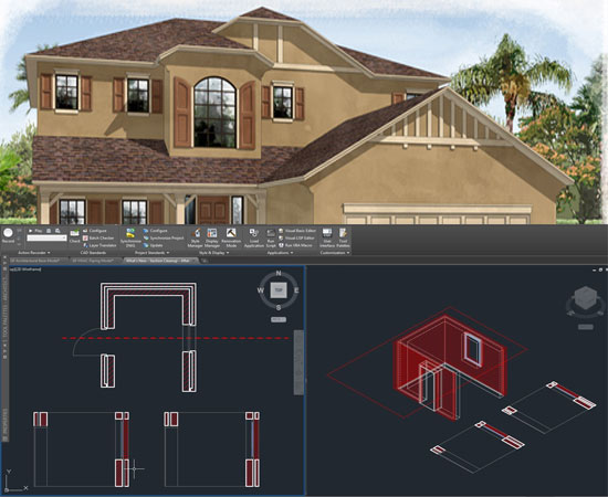
Mufasu CAD presents a useful tutorial for CAD professional. In this tutorial, one can familiar with creating 3d broken wall as well as inserting materials to wall style with some easy to follow steps.


~~~~~~~~~~~~~~~~~~~~
Published By
Rajib Dey
www.bimoutsourcing.com
~~~~~~~~~~~~~~~~~~~~

Saturday, August 30, 2014

The importance of 3D PDF

What is the best way to share technical data with stakeholders outside of engineering? One of the issues with sharing technical data is the fact that many of the intended recipients are non-technical, that means they don’t use 3D CAD. The types of users involved can also vary widely in terms of the type of devices they would be receiving the data on, such as desktops, laptops or mobile devices, such as phones or tablets.

3D PDF

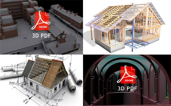
The solution is 3D PDF. Everyone knows about the ubiquitous PDF and how useful it is when sharing documents. In fact, everyone has the Adobe PDF reader. What may not be known is that the standard Adobe PDF Reader (that everyone has) can display interactive 3D data and can contain other related information as well – think of it as a container – more on that later.

What makes 3D PDF an ideal solution?

It is that it is easy to use, free, already is on the computer (and apps are available for tablets), and enables anyone inside or outside of a company to easily access and use the valuable 3D engineering data via their desktop or mobile device–without additional licensing costs.

The 3D PDF Components are sharing of your interactive 3D model is only the beginning. The 3D PDF is a container. Adobe designed a tremendous amount of flexibility into this powerful file format. Other data structures that might be included could be any that have a relationship to the CAD assembly model data—for instance, 1. Part Lists 2. The procedures for completing a task, also known as work instructions or tasks 3. The snapshots and animations of the steps of an assembly process or a service procedure.

Using the 3D PDF standalone or part of PLM/PDM processes

It doesn’t matter if you are a small engineering company or a Fortune 100 manufacturing company, using 3D PDF for sharing interactive 3D models with related information (including PMI) is probably the best way to share with any stakeholder. If you are a big company, you will most certainly have a PLM or PDM system, and the 3D PDF can easily be tucked in with all the rest of your files. If you are a small company, the 3D PDF can become a mini PDM system using its container capabilities to hold all of the above items as well as the original CAD data format and neutral formats, such as IGES and STEP.

There are many 3D PDF generation solutions on the market today — most simply convert CAD geometry– that’s all. The more robust solutions usually require scripting and programming. Lattice Technology offers a solution that enables a person without CAD experience and without programming or scripting to easily and quickly create these powerful 3D PDFs with extended information. The solution uses a template approach, which allows users to establish standards for their 3D PDFs.

The importance of 3D PDF

~~~~~~~~~~~~~~~~~~~
Published By
Rajib Dey
~~~~~~~~~~~~~~~~~~~
Tuesday, August 5, 2014

Creating 3D Model from Scan to BIM

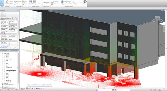
The recently released IMAGINiTs Scan to BIM 2014.1 software for renovation and retro?t projects, and which is available on a rental basis builds upon the Autodesk Revit platform to offer additional point cloud functionality and modeling data that can be relied and validated. This latest version of the Scan to BIM software aids users in creating 3D building information model (BIM) in Autodesk’s Revit building design software from point cloud data.

With Scan to BIM users can view point clouds in Revit more precisely and create as well as validate any model from a point cloud with automated recognition and placement of architectural elements like walls and columns, as well as MEP elements like pipes, conduits, ducts, etc. Besides, it is compatible with Revit 2012, 2013 or 2014. Users can also rent Scan to BIM on a quarterly or yearly basis for any specific project.

Capable of creating native Revit geometry from a point cloud and analyzing the differences between point cloud and the model geometry, Scan to BIM includes the following features-

  • Scan to BIM provides with tools to aid with creation of Revit elements that include: Walls (straight or arc), Columns (rectangular or round), Embedded Curtain Walls, Pipe, Conduit and Duct (rectangular or round), and Levels. Construction geometry to support other element types. Clean topography extraction.

  • Helps interference or clearance detection for geometry vs. point cloud.

  • Available with workflow-based tools that help setting up and working on model with the point cloud.

  • Viewing enhancements to create useful views quickly to step through the project and options to toggle point cloud visibility.

  • Align as well as extend the prevailing geometry to match the point cloud.

  • Measuring points within the scan to find correct dimensions promptly.

  • By comparing the Revit elements against the point cloud user can visualize the accuracy.

  • The ability to export and import data in a format that can be understood by electronic surveying equipment, so that users can read in survey data for as-built conditions, as well as exporting design data for field verification.

  • Supporting floating network licenses.

Creating 3D Model from Scan to BIM

~~~~~~~~~~~~~~~~~~~~~
Published By
Rajib Dey
~~~~~~~~~~~~~~~~~~~~~

Monday, August 4, 2014

Learn to make as well as import styles through Style Manager in AutoCAD Architecture or AutoCAD MEP

Issue: There is no option for applying style in a file. But one can make his own styles or import available styles from another file. To perform this, apply the following tricks:-
Solution:

 1. To tailor styles on the basis of the Standard styles:-


  •          Click on the style manager to open it.

  •          Broaden a Style Category (eg. Wall Styles).

  •          Opt for the Standard style in the category.

  •          To replicate the standard style, apply the Copy and Paste buttons situated in the       tool bar.

  •           Underneath the original style, there will be a Standard (2) style.

  •           Change the name of the style.

  •          Modify the properties of the style with the tabs located at the right. The tabs              range  from General, Design Rules, Overrides, Materials, Classifications, Display        Properties, and Version History.

 2. To import aceessible styles from another drawing file:


  •       Click and open the Style Manager (STYLEMANAGER).

  •      Navigate and open the file that contains the existing styles through the Open menu in the tool bar.

  •     The drawing and its styles will be visible in the file tree underneath the existing drawing.

  •        Extend a Style Category (eg. Wall Styles).

  •     In the existing drawing, drag and drop specific styles into the related category or drag and drop the full category to copy all styles.


The default location for the Imperial Architecture can be found below:-
C:\ProgramData\Autodesk\ACA 201x\enu\Styles\Imperial

The default location for the Imperial MEP content can be found below:-
C:\ProgramData\Autodesk\MEP 201x\enu\Styles\Imperial

For metric or other local content, choose the exact folder within the Styles folder.

Keep in mind that this folder is hidden and in order to get the files inside the hidden folder, activate Windows Explorer.

3. If no style prevails in a category:


  •          Right-click on the category (eg. Wall Styles).

  •          Click on "New" to create a new style.

  •          Modify the properties of the style with the tabs located at the right.


AutoCAD Architecture or AutoCAD MEP

~~~~~~~~~~~~~~~~~~~
Published By
Rajib Dey
~~~~~~~~~~~~~~~~~~~

Sunday, August 3, 2014

How to leverage sketchup data in Revit for topography

DavidRBeach comes with an exclusive tutorial to learn the detailed procedures for generating topography for a project massing model by leveraging sketchup data in Revit for topography.


~~~~~~~~~~~~~~~~~~~~~
Published By
Rajib Dey
~~~~~~~~~~~~~~~~~~~~~

Friday, August 1, 2014

Revit 2014 - Cap Open Ends For Duct and Pipe

This exclusive video tutorial is presented by Stlouis Revitusergroup. New feature in 2014 - You can now easily cap off ends of ducts or pipes.


~~~~~~~~~~~~~~~~~~~~~
Published By
Rajib Dey
~~~~~~~~~~~~~~~~~~~~~